Facebook Twitter Instagram
    Trending
    • Testing of Circuit Breaker
    • Faults in Distribution Lines
    • Distribution System Overview
    • Transmission Towers
    • TRANSFORMER MAINTENANCE
    • OVERVIEW OF GENERATOR PROTECTION
    • TYPES OF EXCITATION SYSTEM
    • Functions and Performance Requirements of Excitation Systems
    Learn With Electric Know How
    • Home
    • Generation
      • Hydropower Station
      • Thermal Power Station
      • DISTRIBUTED ENERGY SOURCES
      • Diesel Generator
      • Industrial Tools
      • DC System-Generating Stations
    • Transmission
      • High Voltage DC Transmission
      • High Voltage AC Transmission
      • Three Phase Control Wiring
    • Distribution
      • Distribution System Overview
      • Faults in Distribution Lines
    • Protection
      • Power System Protection
        • Types of Fault in Power System
        • Circuit Breaker
      • OVERVIEW OF TRANSFORMER PROTECTION
        • Differential Protection of Transformer
      • OVERVIEW OF GENERATOR PROTECTION
      • Distance Protection
      • Electrical Safety
    • Switchgear
      • Electrical Sub-Station
        • BATTERY SYSTEM IN GRID SUBSTATION
        • Operation of Float Cum Boost Charger
        • Protection Circuitry of Battery Charger
        • Transformer
          • INSULATION RESISTANCE OF TRANSFORMER
          • WTI AND OTI in Power Transformer
          • Transformer Oil Dielectric strength
        • Sub-Station Operation
        • Multiplying Factor for Energy Meter
      • Current Transformer
      • Potential Transformer
      • Isolator in Substation
      • Electrical Busbar
      • Insulators
      • Clamps and Connectors
      • Fire Fighting System
      • Lightening Arrester
      • Gas Insulated Substation
        • Local Control Cubicle
        • SF6 circuit breaker gas compartment
    • Q&A
      • FAQS ON CT
      • POWER SYSTEM
      • FAQ ON BUSBAR
    Learn With Electric Know How
    Home»Generation»Local Control Cubicle
    Generation

    Local Control Cubicle

    madhusmitaBy madhusmitaNovember 24, 2022Updated:November 25, 2022No Comments2 Mins Read
    Facebook Twitter Pinterest LinkedIn Tumblr Email
    Share
    Facebook Twitter LinkedIn Pinterest Email

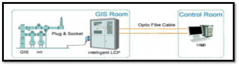
    It is the main controlling part of GIS and power and control lines of auxiliary cables, Current and potential transformers, alarms, and circuit breakers are brought from GIS to the LCC module for control purposes. Each circuit breaker has one local control cabinet for its purposes.

    These circuit breakers monitor the respective bays and are usually placed in the front of the bay.

    Structure:

    It is enclosed in a metal cabinet and its sheet if of steel. It is standing freely and has a lockable door with lights. It has control switches.

    Other components:

    • AC Supply terminal
    • DC Supply terminal
    • Circuit breakers
    • Close and Open Switches
    • Grounding Switches

    What are the interlocks provided in LCC of GIS?

    The grounding switch for high speed is interlinked with its circuit breaker

    The feeder grounding switch is interlinked with its own circuit breaker and disconnect switch.

    Electrical and mechanical interlock is also provided. It is provided disconnect and grounding switch operation.

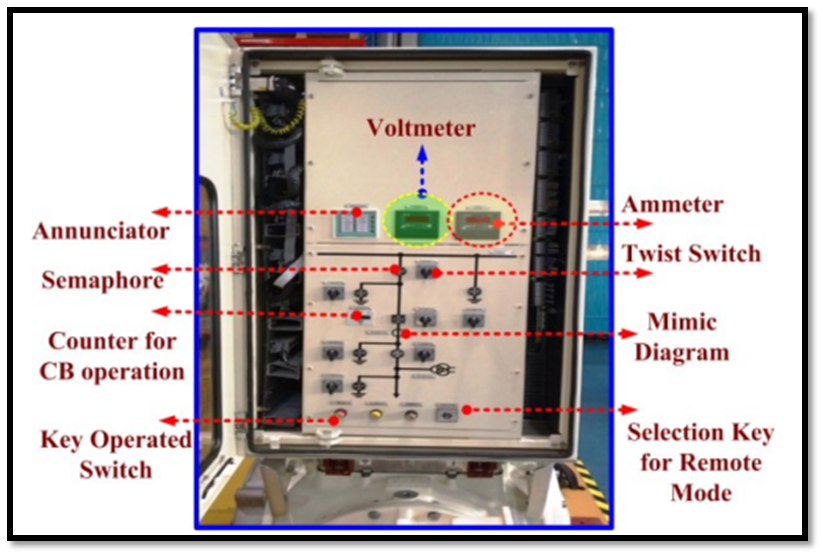
    Modern Local Control Cabinet:

    In the current time, we have a combination of LCC to achieve modern and intelligent switchgear substations. We have LCC for monitoring and for protection purposes. Intelligent control panels are also available for advancement in GIS and proper monitoring.

    We have secondary functions in GIS such as control and measurement that can realize the data for analysis, online monitoring, interlocking, etc. Intelligent devices are more advanced and they replace the relays, contactors, and alarm lights that make their primary and secondary combination.

    They measure the following parameters:

    • Bay voltage Signal
    • Bay current Signal
    • Voltage calculations
    • Current calculations
    • Power
    • Power factor
    • Fundamental frequency odd harmonics

    We have a display system and it sends data via Ethernet. Ethernet is actually data rate for transfer data. So signal cables are reduced than traditional LCC

    Share. Facebook Twitter Pinterest LinkedIn Tumblr Email
    Previous ArticleSF6 circuit breaker gas compartment
    Next Article Sub-Station Operation
    madhusmita
    • Website
    • Facebook
    • Instagram
    • LinkedIn

    Related Posts

    TYPES OF EXCITATION SYSTEM

    December 23, 2022

    Functions and Performance Requirements of Excitation Systems

    December 23, 2022

    Thermal Power Station

    December 18, 2022

    Comments are closed.

    Recent Posts
    • Testing of Circuit Breaker
    • Faults in Distribution Lines
    • Distribution System Overview
    • Transmission Towers
    • TRANSFORMER MAINTENANCE
    Recent Comments
    • Faults in Distribution Lines - Learn With Electric Know How on Distribution System Overview
    • POWER SYSTEM - Learn With Electric Know How on Distribution System Overview
    • POWER SYSTEM - Learn With Electric Know How on Thermal Power Station
    • Basics of Power System Protection - Learn With Electric Know How on OVERVIEW OF GENERATOR PROTECTION
    • Functions and Performance Requirements of Excitation Systems - Learn With Electric Know How on TYPES OF EXCITATION SYSTEM
    Archives
    • March 2023
    • December 2022
    • November 2022
    Categories
    • Distribution
    • Generation
    • Protection
    • Q&A
    • Switchgear
    • Transmission
    • Uncategorized
    Meta
    • Register
    • Log in
    • Entries feed
    • Comments feed
    • WordPress.org

    Quick Links

    • Home
    • About Us
    • Contact Us

    Post Categories

    • Generation
    • Transmission
    • Distribution
    • Protection
    • Switchgear
    • Q&A

    Vip Link

    • Privacy Policy
    • Disclaimer
    • Terms and Conditions

    Contact Us

    • [email protected]
    Youtube Linkedin