

INTRODUCTION
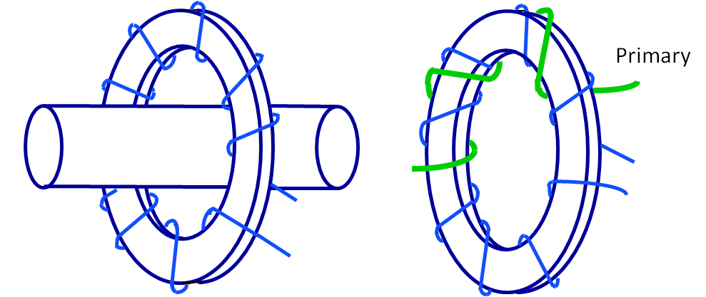
A transformer for use with electrical measuring instruments and/or electrical protective devices for the transformation of current and in which the current in the secondary winding in normal conditions of use is substantially proportional to the current in the primary winding and differing it from an angle which is approximately zero for an appropriate direction of the connections. This electrical Current Transformer(CT) training course introduces basic safe operational and field diagnostics of CTs with a focus on safe operation, testing, and maintenance of the CTs normally installed in substations.
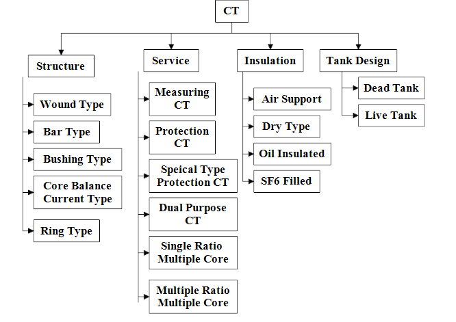
How are current transformers Classified?
CTs are classified according to structure, service, insulation, and tank design.
Different Parts of Current Transformer
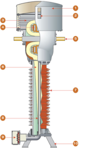
1. Top cover
2. Oil level indicator
3. Oil expansion device
4. Metal box LV screen and cores
5. Bar-type or wound-type primary
6. Paper-oil insulation
7. Porcelain insulator
8. LV screens
9. Secondary terminal box
10. Base
| Parts of CT | Material Used for Construction |
| PRIMARY WINDING | ring type or hairpin type(high purity, annealed, high conductivity electrolytic copper) |
| SECONDARY WINDINGS: | Suitably insulated copper wire of electrolytic grade |
| PRIMARY TERMINALS | heavily tinned electrolytic copper or Aluminium alloy of 99.9% conductivity |
| SECONDARY TERMINALS | The studs, nuts, and washers shall be of brass, duly nickel plated. |
| Core | Core laminations shall be of CRGO silicon steel or other equivalent alloys |
| TANK | high-quality steel |
| PORCELAIN HOUSING | homogeneous, vitreous porcelain of high mechanical and dielectric strength |
| INSULATING MEDIUM ( OIL TYPE) | purified oil |
| Fittings and Accessories | Oil level gauge. Oil filling hole and cap. Pressure relieving device. Phase terminal connectors. Lifting lugs for core |
DESIGN AND MANUFACTURING PROCESS OF THE CURRENT TRANSFORMER
The manufacturing process of a 132kV current transformer (CT) typically involves several steps. Here is a general overview of the manufacturing process:
- Design and Engineering: The first step is to have a detailed design and engineering plan for the 132kV CT. This includes determining the specifications, such as rated current, accuracy class, burden, insulation requirements, and physical dimensions. The design also includes the core material, turns ratio, winding configuration, and housing design.
- Material Procurement: Once the design is finalized, the necessary materials are procured. This includes sourcing the core material, insulation materials, winding wire, bushings, terminals, and other components required for the CT.
- Core Manufacturing: The core of the CT is typically made of high-quality silicon steel laminations. The laminations are cut and stacked to form the core shape specified in the design. The stacked core is then clamped and insulated to minimize core losses and improve the magnetic properties.
- Winding: The primary and secondary windings are manufactured using insulated copper or aluminum wire. The winding wire is carefully wound around the core following the specified turns ratio and configuration. Insulation materials, such as insulation tape or varnish, are applied between the windings and layers to ensure proper insulation and prevent short circuits.
- Assembly: The core with windings is then assembled with other components, such as bushings and terminals. The bushings provide electrical connections for the primary and secondary windings, and the terminals allow for external connections to the CT. The assembly is securely mounted within a housing or enclosure designed to provide mechanical protection and environmental sealing.
- Insulation and Impregnation: The CT is subjected to insulation tests to ensure proper electrical insulation between windings and components. Insulation materials, such as epoxy resin or oil, may be used to impregnate the CT for enhanced insulation and to improve thermal performance.
- Testing and Calibration: After manufacturing, the CT undergoes a series of tests to verify its performance and accuracy. This includes ratio tests, burden tests, accuracy tests, insulation tests, and other electrical tests specified by relevant standards. The CT may also be calibrated to ensure accurate measurement and protection capabilities.
- Quality Control and Compliance: Throughout the manufacturing process, stringent quality control measures are implemented to ensure that the CT meets the specified design requirements and complies with relevant standards and regulations. This includes inspections, documentation, and adherence to quality management systems.
- Packaging and Shipping: Once the CT passes all tests and quality checks, it is carefully packaged to protect it during transportation. Appropriate labeling and documentation are prepared, and the CT is shipped to the designated location.
Tests (Type Test/Special Test)Conducted for CT
- Lightning Impulse Voltage Test.
- High Voltage power frequency wet withstands voltage Test.
- Short-time current test.
- Temperature rise test.
- Instrument Security Factor Test.
- IP-55 Test on Secondary Terminal Box.
- Radio Interference voltage test.
- Corona Extinction test.
- Thermal stability test.
- Thermal Co-efficient test.
- Fast transient test.
- Seismic withstand test.
- Mechanical terminal load on the bushing.
- Magnetization and internal burden tests..
- Effectiveness of sealing tests.
- Capacitance and dielectric loss angle test.
Routine tests conducted for CT
- Verification of Terminal Marking and polarity.
- Appearance and Dimensional Check.
- Measurement of Insulation Resistance.
- Power Frequency Dry withstands Tests on Primary and Secondary winding including primary intersections.
- Over – Voltage Inter turn test.
- Partial discharge Test for 400 KV,220 KV, and 132KV C.TS
- Knee point voltage and Excitation current measurement for ‘PS’ class cores.
- Secondary winding resistance measurement.
- Determination of errors.
- ISF Test.
- Leakage Test.
- Magnetization Characteristics of the Current Transformers.
- Turn ratio error on ‘PS’ class cores.
- Measurement of capacitance for 400 KV,220KV and 132KV C.TS.
- Measurement of the tan delta at 0.3, 0.7, 1.0, and 1. lUм/√3 for 400 KV,220KV & 132KV C.Ts.
CT Console box
It acts as the necessary interface between the equipment and the control room panel. The three-phase control wiring takes place for the purpose of the specific use of the CT.
Reasons for CT Failures
moisture entry into solid insulation
opening of the secondary winding
opening of tan delta point
dielectric failure due to premature aging
lOther dielectric failures due to the improper wrapping of paper, improper flux distribution, etc.
Conclusion
Current Transformers are the sensors for the electrical system and play the most vital role in the protection and measurement Circuit.
