

This electrical transformer training course introduces basic safe operational and field diagnostics of power transformers. This includes a focus on safe operation, testing, and maintenance of the power transformers normally installed in substations.
History of Power Transformers:
Transformers started in 1880, and in property of mutual induction. Initial transformers had lesser efficiency and they had large sizes but later on, power transformers with more efficiency and with lesser size has been manufactured.
Up-to the year of 1880, numerous manufacturers introduced 800kVA and more power-rating transformers. In 1970, only unit rating up to 1100MVA was introduced.
Definition
A transformer is a static device that transfers electrical energy from one circuit to another through inductively coupled electrical conductors.
Electrical Transformers serve the crucial function of transforming voltage potential to a higher or lower value to meet the appliances and machinery voltage level requirements.
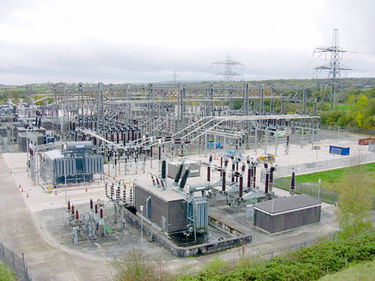
Improper use, maintenance, and neglect of power transformers can cause heavy losses to businesses as well as to the environment.
Components of a Transformer
- Steel Tank is one of the most important parts of the transformer. The steel tank is cylindrical or cubicle and holds the core and other important parts of the transformer. It is filled with insulating oil and painted on both sides (internally and externally) for protection.
- Laminated Core-Soft iron of steel makes the core part of the transformer. The core provides a continuous path to the flow of magnetic flux, reducing eddy currents and hysteresis losses. Copper losses increase by increasing the diameter of the core.
Why we do not use solid material in the core?
This is important to note that we don’t use solid material in the core because there are energy losses as the disadvantage of using solid material. We laminate the core to reduce the eddy currents and energy losses.
Winding–
- Copper turns make winding of the transformer together and insulation is provided to each winding for protection purposes. We have two windings here in the transformer: Primary winding for input voltages and Secondary winding for output voltage
- Tap Changer-Tap changer is used to regulate the output voltage by increasing or decreasing the tap number and Voltage drops because of an increase in load at the constant MVA rating of the power transformer.
- The Oil Conservator-Conservator tank is simply a cylindrical tank mounted on the roof of the transformer main tank. It is used to provide enough space for the oil in the transformer to spread after its volume increase in the main tank . Such a condition arises only when the transformer is loaded and the winding temperature rises.
- Cooling tubes: As the name indicates, these tubes work to cool down the transformer oil. Oil naturally circulates in tubes or forcefully.
- Bushing-The material used in transformer bushing is mainly porcelain. But for voltages of hundreds to thousands of volts, the ceramic bushing is used and very high voltage bushings are usually made of polymer, polymeric, or composite. The bushing terminal is the point of connection of the transformer with the external power circuit (it may be incoming or outgoing). The number of bushing in a transformer depends on the number of phases…For example, 3phase transformer the total number of bushing is 6 (the incoming phase has 3 and the outgoing phase has 3), and for 2 phase has total of 4( 2 incoming and 2 outgoings)
- Breather oil oil-insulated power transformer is oil-filled up to about half of its conservator tank and the rest with air. The conservator tank is fitted with a ‘breather’ through which air is expelled (breathed out) when the transformer is loaded with the losses causing the oil temperature to increase and expand. During light load conditions, oil cools down and contracts in volume so air is breathed in from the atmosphere. This air contains moisture and the moisture is absorbed by ‘silica gel’ crystals kept in the breather and then allowed to enter the conservator tank.
- Explosion Vent-Explosion vent is provided to give protection against the excessive pressure that may develop inside the transformer due to internal fault. On specific requirements, the explosion vent is provided with two diaphragms one at the bottom (near the tank) and the other at the top. If excessive pressure is developed in the tank, both diaphragms will rupture and oil in tanks will be thrown out through the vent. One pressure equalizer pipe is provided between the explosion vent and the conservator to maintain equal pressure in the empty spaces of the vent and conservator. In this case, an oil level indicator is provided on the explosion vent to indicate a rupture of the bottom diaphragm.
- Buchholz Relay-Buchholz relay is used as a protective device used for the protection of the transformer against the fault that occurs inside the transformer. It is actually a gas-actuated relay connected between the main tank and the conservator. It gives protection against inter-turn fault and core faults.
Usage of transformer
Two-winding transformers are generally used when the ratio between high voltage and low voltage is greater than 2. Using an autotransformer will be cost-effective when the ratio between high voltage and voltage is low. lower than 2. Again, a single three-phase transformer is more cost-effective than a series of three single-phase transformers in a three-phase system. But a three-phase transformer is a bit difficult to transport and must be completely shut down if one of the phase windings fails.
What is the role of the transformer in the Power system?
Low-voltage power generation is very cost-effective. Theoretically, this low-voltage supply power could be transmitted to the receiving end. This low voltage source, if transmitted, results in more current, thus causing more line losses.
But if the voltage level of the power supply is increased, the current of the power supply will decrease, resulting in a decrease in ohmic or I2R losses in the system, a decrease in the conductor cross-section, i.e. a decrease in the capital cost of the system and it also improves the voltage regulation of the system.
For this reason, low-end power must be increased for efficient power transmission. This is accomplished by an upgraded transformer on the generating side of the power system network. Since this high-voltage power cannot be supplied directly to the consumer, it must be reduced to the desired level at the receiving end using a step-down transformer. Therefore, transformers play an important role in power transmission.
