
A thermal power station, also known as a thermal power plant or simply a thermal plant, is a facility that generates electricity by burning fossil fuels or other heat sources to produce steam, which drives a turbine connected to an electrical generator. Thermal power stations are one of the most common types of power plants globally and have been a major source of electricity generation for many decades. Here is an overview of a typical thermal power station:.
The coal, brought to the station by train or other means, travels from the coal handling plant by conveyor belt to the coal bunkers, from where it is fed to the pulverizing mills which grind it as fine as face powder. The finely powdered coal mixed with preheated air is then blown into the boiler by a fan called Primary Air Fan where it burns, more like a gas than as a solid in a convectional domestic or industrial grate, with an additional amount of air called secondary air supplied by Forced Draft Fan. As the coal has been grounded so finely the resultant ash is also a fine powder. Some of this ash binds together to form lumps which fall into the ash pits at the bottom of the furnace. The water-quenched ash from the bottom of the furnace is conveyed to pits for subsequent disposal or sale. Most of the ash, still in fine particle form is carried out of the boiler to the precipitators as dust, where it is trapped by electrodes charged with high-voltage electricity. The dust is then conveyed by water to disposal areas or to bunkers for sale while the cleaned flue gases pass on through ID Fan to be discharged up the chimney.
Meanwhile, the heat released from the coal has been absorbed by the many kilometres of tubing which line the boiler walls. Inside the tubes is the boiler feed water which is transformed by the heat into steam at high pressure and temperature. The steam super-heated in further tubes (Super Heater) passes to the turbine where it is discharged through the nozzles on the turbine blades. Just the energy of the wind turns the sail of the windmill, so the energy of the steam, striking the blades, makes the turbine rotate.
Coupled with the end of the turbine is the rotor of the generator – a large cylindrical magnet so that when the turbine rotates the rotor turns with it. The rotor is housed inside the stator having heavy coils of copper bars in which electricity is produced through the movement of the magnetic field created by the rotor. The electricity passes from the stator winding to the step-up transformer which increases its voltage so that it can be transmitted efficiently over the power lines of the grid.
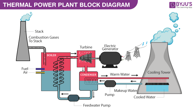
The steam which has given up its heat energy is changed back into the water in the condenser so that it is ready for re-use. The condenser contains many kilometres of tubing through which the colder is constantly pumped. The steam passing around the tubes loses the heat and is rapidly changed back to the water. But the two lots of water (i.e. boiler feed water & cooling water) must NOT MIX. The cooling water is drawn from the river, but the boiler feed water must be absolutely pure, far purer than the water we drink if it is not to damage the boiler tubes. Chemistry at the power station is largely the chemistry of water.
To condense large quantities of steam, a huge and continuous volume of cooling water is essential. In most power stations, the same water is to be used over and over again. So the heat which the water extracts from the steam in the condenser is removed by pumping the water out to the cooling towers. The cooling towers are simply concrete shells acting as huge chimneys creating a draught (natural/mechanically assisted by fans) of air. The water is sprayed out at the top of towers and as it falls into the pond beneath it is cooled by the upward draught of air. The cold water in the pond is then circulated by pumps to the condensers. Inevitably, however, some of the water is drawn upwards as vapours by the draught and it is this which forms the familiar white clouds which emerge from the towers seen sometimes.
Summary
Thermal power stations have played a significant role in providing reliable electricity generation, but they also face challenges related to environmental impact, fuel availability, and the transition to cleaner energy sources. Many power utilities are investing in cleaner and more efficient technologies, such as advanced gas turbines and carbon capture and storage (CCS), to reduce their environmental footprint and adapt to changing energy trends.

1 Comment
Pingback: POWER SYSTEM - Learn With Electric Know How