Close Menu
    Facebook X (Twitter) Instagram
    Trending
    • INTRODUCTION TO SUBSTATION EARTHING
    • Maintenance of GIS (Gas-Insulated Switchgear)
    • Nameplate Detail of Isolators/Dis-connectors- A Detail Guide
    • What is the use of an anti-pumping relay?
    • Key Components of Control & Relay Panel
    • TRANSMISSION TOWER CONFIGURATION
    • Nameplate Detail of Current Transformer – A Detail Guide
    • Major parameters of a circuit breaker
    Electric Know How
    • Home
    • Generation
      • Hydropower Station
      • Thermal Power Station
      • DISTRIBUTED ENERGY SOURCES
      • Diesel Generator
      • Industrial Tools
      • DC System-Generating Stations
    • Transmission
      • High Voltage DC Transmission
      • High Voltage AC Transmission
        • Transmission line – An Overview
        • TRANSMISSION TOWER CONFIGURATION
      • Three Phase Control Wiring
    • Distribution
      • Distribution System Overview
      • Faults in Distribution Lines
    • Protection
      • Power System Protection
        • Types of Fault in Power System
        • Relay Setting Calculation for Substation
        • Circuit Breaker
          • Major parameters of a circuit breaker
        • Key Components of Control & Relay Panel
      • OVERVIEW OF TRANSFORMER PROTECTION
        • Differential Protection of Transformer
      • OVERVIEW OF GENERATOR PROTECTION
      • Distance Protection
      • Electrical Safety
    • Switchgear
      • Electrical Sub-Station
        • BATTERY SYSTEM IN GRID SUBSTATION
        • Operation of Float Cum Boost Charger
        • Protection Circuitry of Battery Charger
        • Power Transformer
          • INSULATION RESISTANCE OF TRANSFORMER
          • WTI AND OTI in Power Transformer
          • Transformer Oil Dielectric strength
        • Sub-Station Operation
        • Multiplying Factor for Energy Meter
      • Current Transformer
        • Nameplate Detail of Current Transformer – A Detail Guide
      • Potential Transformer
      • Isolator in Substation
      • Electrical Busbar
      • Insulators
      • Clamps and Connectors
      • Fire Fighting System
      • Lightening Arrester
      • Gas Insulated Substation
        • Local Control Cubicle
        • SF6 circuit breaker gas compartment
    • Q&A
      • FAQS ON Current Transformer
      • POWER SYSTEM
      • FAQ ON BUSBAR
    Electric Know How
    Home»Protection»Distance Protection
    Protection

    Distance Protection

    madhusmitaBy madhusmita18 December 2022Updated:16 March 2023No Comments4 Mins Read
    Facebook Twitter Pinterest LinkedIn Tumblr Email
    Share
    Facebook Twitter LinkedIn Pinterest Email

    Transmission lines are used to transmit electric power from one place to far distant places where power has to be consumed. We used long towers and conductors to transmit the power. So this is natural or need of the process that transmission conductors must be protected in order to keep working.

    Introduction of Distance protection:

    Distance protection is mainly used for transmission lines. We use a relay system for tripping in case of fault and then that relay gives a tripping signal to its respective circuit breaker and then that faulty portion gets separated from the healthy portion.

    We also use an overcurrent relay for protection but due to some limitations, we prefer to use a distance relay. In over current relay we fixed the pickup current value. Fault current depends on source impedance and voltage value. Due to this reason overcurrent relay is not much efficient as distance relay. We should be independent of the type of fault and the characteristics of the generator.

    That’s the reason we go for distance protection. “We have a fixed value of impedance and then we check the impedance between the relay and at the fault point. If the value meets the condition of tripping for a specific impedance value then our breaker will trip for that fault.”

    You can have a look on below diagram:

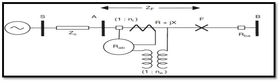
    Here we have source side impedance set valueZs and in the circuit we have Relay, CT (Current transformer) and PT (Potential/Voltage transformer) and Bus A and Bus B.

    F represents the fault happening on the transmission line. At fault, we have current ad voltage values so that will depends on the type of fault. But the ratio of voltage and current will give us the impedance value from the relay point to fault location. So, it is independent of the source or set value of impedance.

    We have a tripping setting mentioned below:

    Vr = Relay voltage

    Ir = Realy Current

    Vr/Ir<Zset then trip the corresponding breaker.

    Not automatically it becomes independent from the characteristics of our system.

    Zr<Zset then the relay will trip.

    Tripping will happen using both the current coil and voltage values. 

    Zr<Zset as ratio of constants is Zset value

    The relay will issue a trip signal for a value less than Zset value. As we are using ratio of values so it will be independent of circuit characteristic values. It is independent of the type of fault, voltage, and source impedance value.

    The relay will compare the value obtained current and voltage using CT and VT.

    Zones of protection:

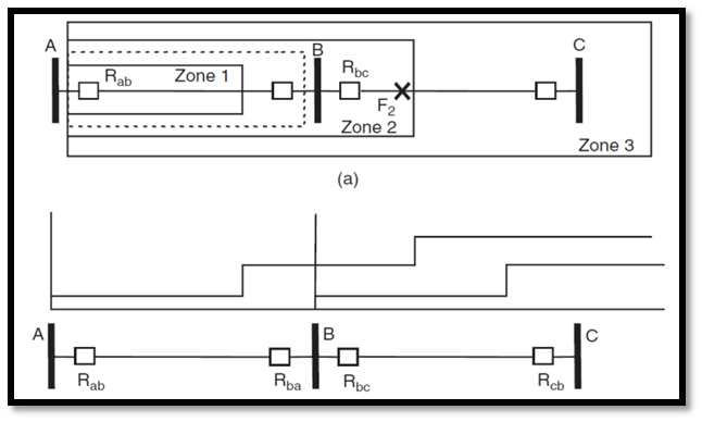
    In this diagram, all relays are provided for protection purposes in the forward diagram. For forward direction, the relay operates in the transmission line direction and bus bar side of relay behaves as the backward direction of a relay.

    Zone-1in the practical concept covers only 80% before the next bus (zone-1), not 100%. This s the actual area covered by the zone-1 relay. The reason is due to DC effect there will be an overreach of the relay and whenever overreach happens, it creates problems. So we skip the 20% of the zone and that 20% will be added in the zone-2 protection relay.

    In Zone-2 20% we cover the remaining area of zone-1 and 40% next part from bus bar B (In above diagram) to avoid overreach conditions.

    Next, all portions will go into zone-3 and hence our transmission lien is protected using zones of relays easily without any disturbance overreaching.  

    In Zone-1 there will be instantaneous tripping when a fault occurs and after a specific time delay of relay. Similar case goes for other zones. There will be more time delay in zone 3.

    Share. Facebook Twitter Pinterest LinkedIn Tumblr Email
    Previous ArticleTrip Circuit Supervision Relay
    Next Article DISTRIBUTED ENERGY SOURCES
    madhusmita
    • Website
    • Facebook
    • Instagram
    • LinkedIn

    Related Posts

    What is the use of an anti-pumping relay?

    22 July 2024

    Key Components of Control & Relay Panel

    25 May 2024

    Nameplate Detail of Current Transformer – A Detail Guide

    21 March 2024

    Comments are closed.

    Recent Posts
    • INTRODUCTION TO SUBSTATION EARTHING
    • Maintenance of GIS (Gas-Insulated Switchgear)
    • Nameplate Detail of Isolators/Dis-connectors- A Detail Guide
    • What is the use of an anti-pumping relay?
    • Key Components of Control & Relay Panel
    Certification Course
    Archives
    • January 2025
    • December 2024
    • August 2024
    • July 2024
    • May 2024
    • March 2024
    • February 2024
    • January 2024
    • November 2023
    • October 2023
    • September 2023
    • August 2023
    • July 2023
    • June 2023
    • May 2023
    • April 2023
    • March 2023
    • December 2022
    • November 2022
    Categories
    • Distribution
    • Generation
    • Nameplate Details
    • Protection
    • Q&A
    • Switchgear
    • testing
    • Transmission
    Electric Volt

    Quick Links

    • Home
    • About Us
    • Contact Us

    Post Categories

    • Generation
    • Transmission
    • Distribution
    • Protection
    • Switchgear
    • Q&A

    Vip Link

    • Privacy Policy
    • Disclaimer
    • Terms and Conditions

    Contact Us

    • [email protected]
    Linkedin