
📘 Introduction
Power factor (PF) is a vital parameter in AC power systems, representing how effectively electrical power is being converted into useful work. In distribution systems, low power factor leads to increased losses, voltage drops, and inefficient utilization of the infrastructure.
This article explains what power factor is, why correction is needed, and the methods used to improve power factor in distribution networks.
🔍 What is Power Factor?
Power Factor=Real Power (kW)Apparent Power (kVA)\text{Power Factor} = \frac{\text{Real Power (kW)}}{\text{Apparent Power (kVA)}}Power Factor=Apparent Power (kVA)Real Power (kW)
- Real Power (kW): The power used by the load.
- Reactive Power (kVAR): Power stored and released by inductive components.
- Apparent Power (kVA): The total power supplied by the source.
🎯 Ideal PF = 1 (or 100%)
But in reality:
- Inductive loads (motors, transformers, etc.) cause lagging power factor (typically 0.7–0.9).
- Capacitive loads can cause a leading power factor.
⚠️ Effects of Low Power Factor
| Problem | Impact on Distribution System |
|---|---|
| Increased current | Higher conductor and transformer losses |
| Voltage drop | Poor voltage regulation |
| Reduced capacity | Limits how much load a line or transformer can support |
| Higher demand charges | Utilities may penalize consumers for poor PF |
| Overheating | Causes stress on cables and equipment |
🎯 Power Factor Correction (PFC)
Power Factor Correction involves adding components to the system that supply reactive power, thereby reducing the demand on the supply.
⚙️ Methods of Power Factor Correction
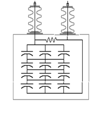
1. Capacitor Banks
Most commonly used method in distribution systems.
| Type | Application |
|---|---|
| Fixed Capacitor Banks | For stable loads |
| Automatic (Switched) Banks | For varying loads (uses contactors or relays) |
| Pole-mounted Capacitors | On rural feeders to support voltage and PF |
📌 Capacitors provide leading kVAR, offsetting lagging reactive power from inductive loads.
2. Synchronous Condensers
- Synchronous motors are running without a mechanical load.
- Expensive but provides adjustable PF correction.
- Used in large substations and industrial settings.
3. Static VAR Compensators (SVC)
- Electronically controlled capacitors and reactors.
- Used in HV and EHV substations for dynamic PF correction.
4. Power Factor Controllers
- Monitor PF in real-time.
- Automatically switch capacitors in/out based on load conditions.
📊 Where to Apply PF Correction?
| Location | Description |
|---|---|
| At the feeder head | Improves local PF, reduces feeder losses |
| At the consumer end | Supports line voltage and system PF |
| In substations | Helps system-wide PF regulation |
| At consumer end | Avoids PF penalties and demand charges |
📈 Benefits of Power Factor Correction
- Lower energy bills (through reduced demand charges)
- Enhanced voltage regulation
- Increased load capacity of the system
- Reduced system losses
- Improved system efficiency and reliability
🛠️ Maintenance Tips for PFC Equipment
- Regularly inspect the capacitor bank terminals and fuses
- Monitor for swelling or heating of the capacitor units
- Use PF controllers with alarms for abnormal operation
- Replace failed stages promptly to maintain correction levels
- Clean and test contactors and relays in switched banks
📌 Conclusion
Power factor correction is essential for efficient distribution system operation. With correct implementation—whether via capacitor banks, controllers, or advanced SVCs—utilities can reduce losses, increase capacity, and ensure stable voltage delivery across the network.
