
In electrical installations, clamps and hardware fittings play a critical role in securing and connecting various components, such as conductors, cables, busbars, and other electrical equipment. These fittings are essential for ensuring the safe and reliable operation of electrical systems. Here are some common types of clamps and hardware fittings used in electrical equipment:
REQUIREMENTS
- Temp rise of clamps should be less than that of the associated conductor
- Mechanical strength should be high enough to withstand the dynamic loads occurring during short circuits and erection.
- Resistant to corrosion due to moisture
- Material:- i) For connecting ACSR Zebra conductor aluminum alloy casting conforming to designation A6 of IS: 617. ii) Bolts, nuts, plain washers, and spring washers for the item: Hot dip galvanized mild steel/stainless steel.
- The clamps shall be designed to withstand the flow of continuous current as follows: ACSR Zebra Conductor- 2000 Amp
- The temperature rise when carrying full load current shall not exceed 45ºC above site ambient temperature of 40ºC.
- Mechanical design:- The Aluminum alloy should be based on an Aluminum – Magnesium – Silicon system.
CONFIGURATIONS
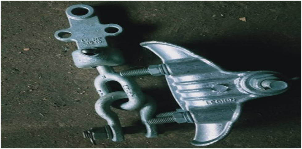
A. Single/ Double Tension hard wire fittings
B. Single/ Double Suspension hard wire fittings
C. T-Clamp/ Compressed Jumper Clamp
D. L- Clamp
E. Bimetallic / Aluminium Straight through Clamp
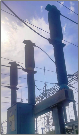
F. Pad Clamp (for Isolator, Post Insulator, CT, Circuit Breaker)
G. Parallel Groove (PG) Clamp
(used for connecting round conductors in T and longitudinal arrangements.)
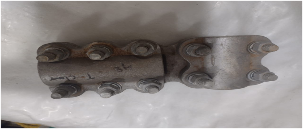
T Clamp
A connector is designed for the purpose of connecting two conductors whose faxes are perpendicular to each other. These are of the following types:
A. Zebra Run Zebra Drop
B. Panther Run Panther Drop
C.Panther Run Zebra Drop
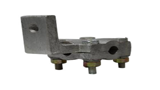
L Type Clamp
PG CLAMP
PG Clamp is provided for secure holding support of transmission conductors. A connector is designed for the purpose of connecting two or more conductors whose axes are parallel to each other.
P G. Clamps for Zebra to Zebra
P. G. Clamps for Zebra to Panther
P. G. Clamps for Panther to Panther
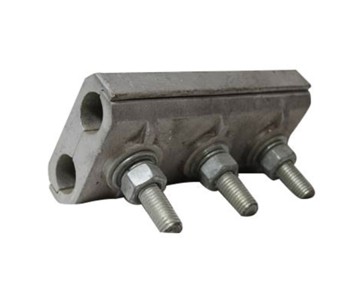
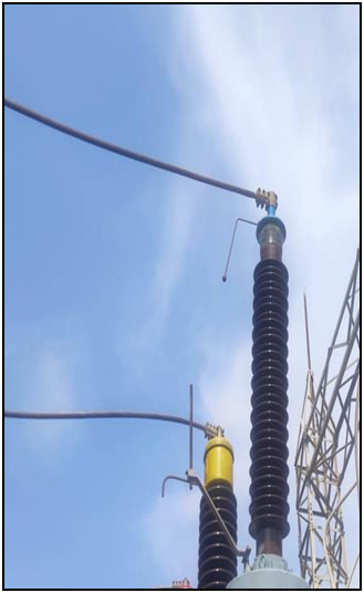
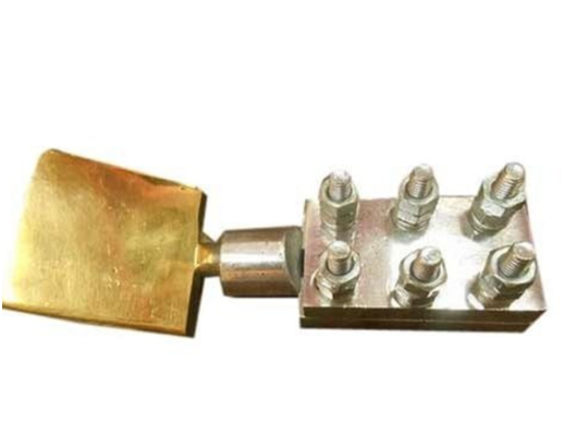
PAD CLAMP
Pad Clamp is commonly used for joining and fastening purposes of isolator and breaker.
Single/ Double Tension hard wire fittings
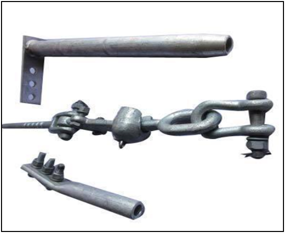
Single/ Double Suspension hard wire fittings
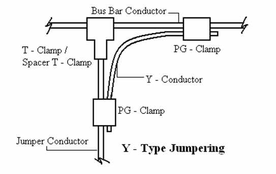
JUMPERING OF CONDUCTORS:
For making Y – type jumpers, the jumper conductor(s) shall be first connected to the bus bar conductor(s) using T – Clamp / Spacer T – Clamp which is suitable for clamping the respective conductors, i.e., bus bar conductor(s) and the jumper conductor(s). Thereafter, the bus bar conductor(s) shall be again connected with the jumper conductor(s) using properly curved & shaped Y – conductor(s) and 2 nos. PG – clamps as shown in the diagram above. The jumpering between equipment shall be done with single / twin / quadruple conductors as per the terminal connectors provided on the equipment. In the case of jumpers for twin and quadruple conductors, the spacers shall also be fitted at a suitable spacing on the jumpers in order to maintain their shape.
Summary
These clamps and hardware fittings are essential for ensuring the proper installation, safe operation, and longevity of electrical equipment and systems. They are designed to meet specific electrical and mechanical requirements and must comply with industry standards and regulations for electrical safety and reliability.
