

1.INTRODUCTION
A Capacitive Voltage Transformer (CVT), also known as a Capacitor Voltage Divider, is a high-voltage instrument transformer used primarily for:
- Voltage measurement
- Protection relays
- Control and monitoring
- Carrier communication (Power Line Carrier Communication – PLCC)
CVTs are commonly used in EHV and UHV substations (132 kV and above) because they are more economical and lighter than electromagnetic voltage transformers (VTs) at high voltages.
2.WORKING PRINCIPLE
Here’s a basic explanation of how a capacitive voltage transformer works:
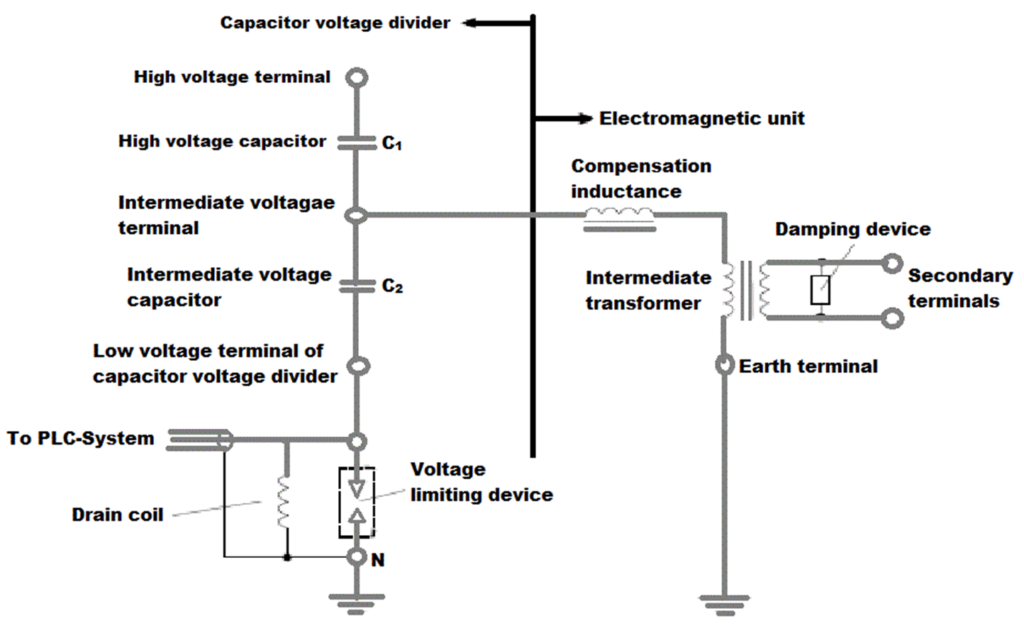
- Capacitor Bank: A CVT consists of a capacitor bank connected in series with the primary circuit. The capacitor bank is designed to have a high capacitance value to provide a low impedance path for the high-frequency components of the voltage.
- Electromagnetic Induction: The primary circuit of the CVT is connected in parallel with the high-voltage line whose voltage is to be measured. The voltage across the primary circuit creates an electric field between the conductors of the primary winding and the grounded conductive shield.
- Secondary Windings: The secondary winding is wound around the conductive shield and is magnetically coupled to the primary winding. The secondary winding is connected to measuring instruments or protective devices.
- Voltage Division: Due to the electric field generated between the primary winding and the conductive shield, a voltage is induced across the secondary winding. The voltage across the secondary winding is proportional to the voltage across the primary circuit and is step-down in magnitude.
- Capacitive Voltage Divider: The capacitive voltage transformer uses a capacitive voltage divider principle to provide a reduced voltage to the secondary winding. The capacitance values and ratios of the capacitors in the capacitor bank are chosen to achieve the desired voltage transformation ratio.
- Output and Accuracy: The voltage across the secondary winding is used as an output to measure or monitor the voltage level. CVTs are designed to provide accurate voltage measurements with minimal distortions and high insulation levels.
📡 3. Advantages of CVT
- Cost-effective at high voltages
- Lightweight and compact compared to electromagnetic VTs
- Can be used for PLCC communication
- Provides electrical isolation
- Suitable for wide frequency bandwidths (for relaying and communication)
🔧 4. Applications
- Voltage Measurement in EHV substations
- Protection Relays input (e.g., distance protection)
- Carrier Communication coupling
- Synchrophasor (PMU) measurement
- Waveform recording and transient analysis
📘5. Standards
- IEC 61869-5 – Instrument transformers – Capacitor voltage transformers
- IEEE C93.1 – Power Line Carrier Applications
- IS 3156 (Part 4) – Indian standard for CVTs
⚠️ 6. Limitations
- Susceptible to transient errors and ferroresonance if not properly damped
- Frequency response may not be suitable for very high-speed relays without tuning
- Requires proper installation and earthing
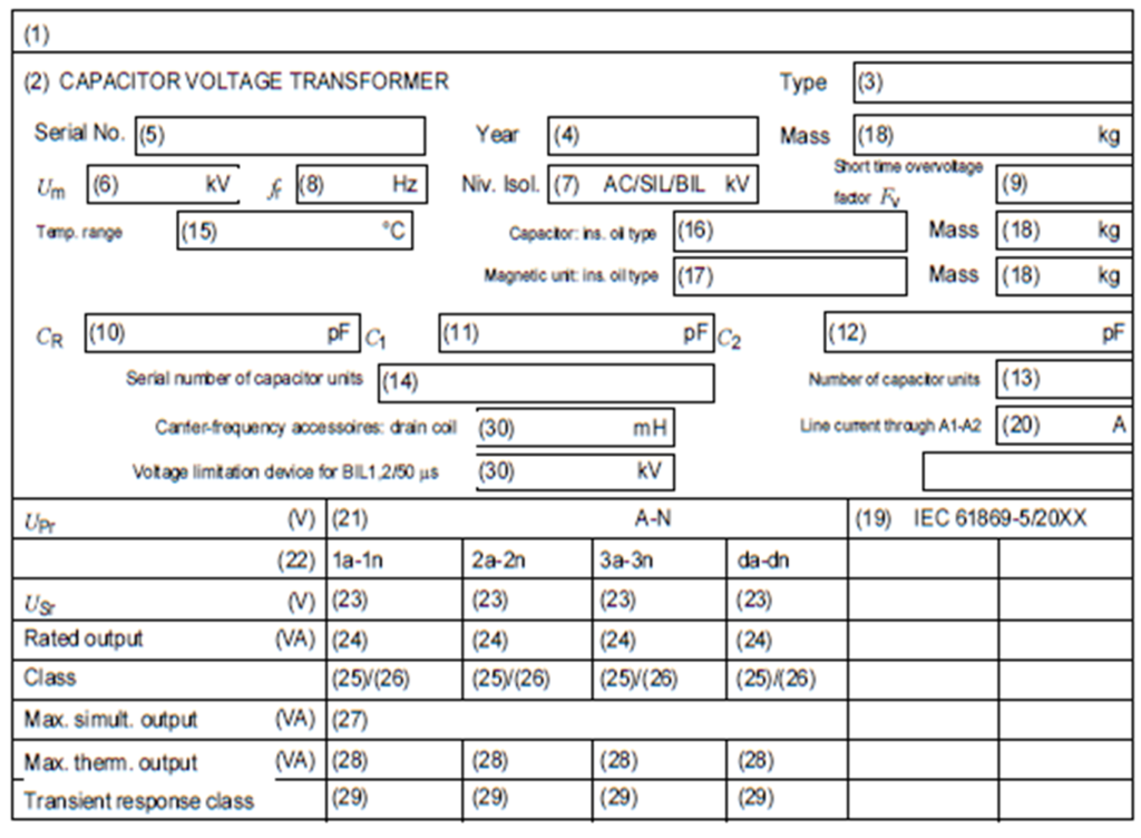
7.NAME PLATE DETAILS OF A CVT
The nameplate details of a CVT (Capacitive Voltage Transformer) can vary depending on the manufacturer and specific model. However, here are some common parameters that you might find on the nameplate of a CVT:
- Voltage Rating: The nameplate will indicate the voltage rating of the CVT which indicates the maximum voltage that the CVT is designed to handle.
- Voltage Transformation Ratio: The nameplate may provide information about the voltage transformation ratio of the CVT. This ratio indicates the relationship between the primary voltage (132kV) and the secondary voltage that the CVT outputs. For example, it might specify a transformation ratio of 132kV/110V.
- Accuracy Class: The accuracy class of the CVT indicates the level of accuracy with which it measures the voltage. It is typically represented as a percentage and specifies the maximum permissible error in voltage measurement. For example, an accuracy class of 0.2 indicates that the CVT has a maximum error of 0.2% in voltage measurement.
- Burden: The nameplate may specify the burden of the CVT, which refers to the maximum load that can be connected to the secondary winding without significantly affecting the accuracy of voltage measurement. It is typically specified in VA (volt-ampere).
- Insulation Level: CVTs operate at high voltages, so the nameplate should indicate the insulation level of the transformer. This information helps in determining the suitability of the CVT for specific applications and the required insulation coordination with other equipment.
- Manufacturer Information: The nameplate will include details about the manufacturer of the CVT, including their name, logo, and contact information.
These are some of the common nameplate details you may find on a CVT. It’s important to refer to the specific nameplate of the CVT you are working with for accurate and detailed information, as different manufacturers may provide additional or slightly different parameters on their nameplates.
8.SUMMARY
It’s important to note that the capacitive voltage transformer is typically used for measuring voltage, and it is not suitable for direct power supply applications. Additionally, CVTs require careful design and calibration to ensure accurate voltage transformation and appropriate insulation levels for safe operation.
