

This electrical Busbar Module introduces basic safe operational busbars in EHT Sub-Stations.
What is the busbar in the substation?
- Busbar is a system where all incoming and outgoing feeders, lines, and transformers are connected through an isolator and breaker.
- The selection of any busbar system depends upon
- Amount of flexibility required in operation.
- Immunity from the total shutdown.
- The initial cost of the installation.
- Load handled by the busbar.
Different Configurations of bus-bar system
- Single busbar
- Main and Transfer Bus
- Double Busbar.
- Ring mains system
SINGLE BUS-BAR
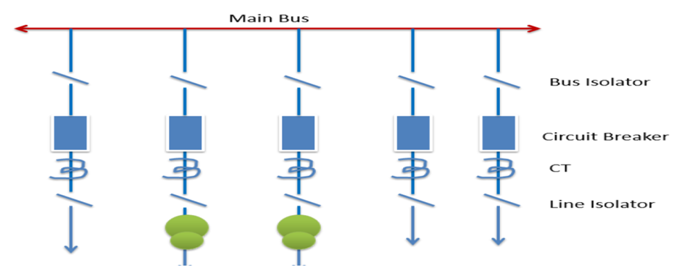
Single Busbar
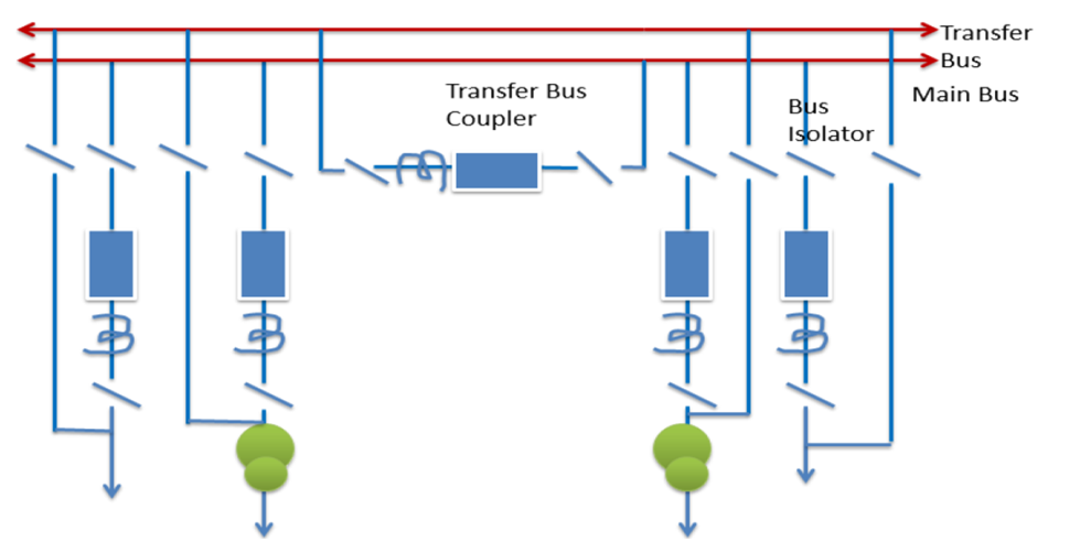
Main and Transfer Bus
With this arrangement, all the feeders are normally on the Main Bus Bar. If at any time, a Line Circuit Breaker/ Transformer circuit breaker Maintenance is required or a breakdown of a Circuit breaker or CTs, that particular feeder/ transformer, can be transferred onto the Transfer Bus. The feeder protection thus gets transferred to the trip Transfer Bus Coupler Breaker. On fault occurrence or maintenance, the entire bus becomes de-energized.
Two main or Double Bus
There are five types of Bus switching schemes double bus bars
- Double busbar system.
- Double bus with sectionaliser system.
- Double bus & transfer bus system.
- Double bus & transfer bus with sectionaliser system.
- One & half breaker system
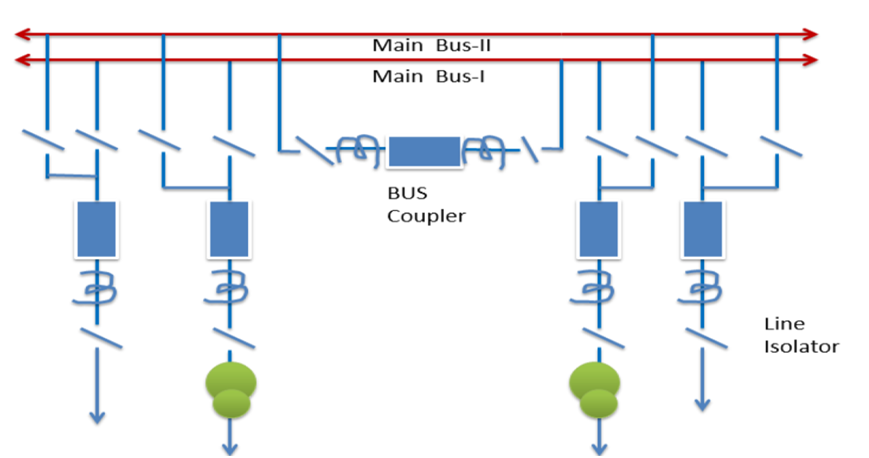
Two main busbar system
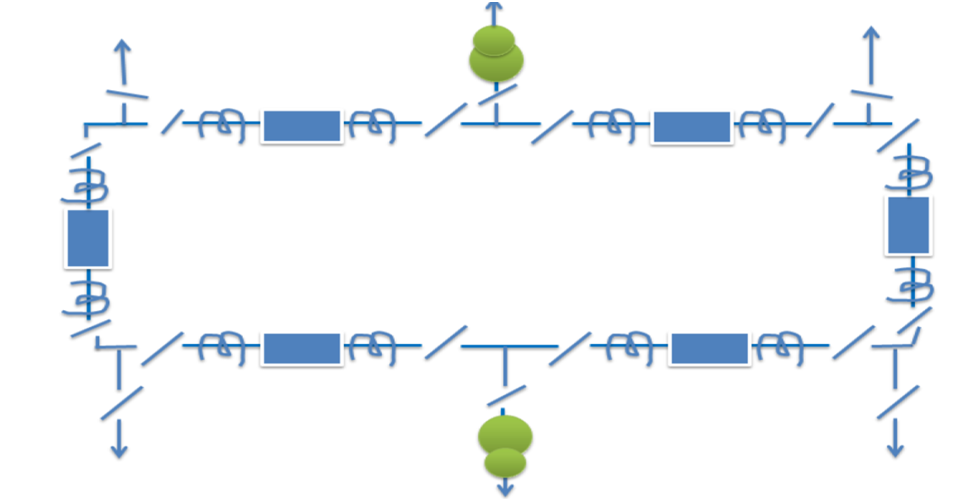
Ring Main Bus System
The schematic diagram of the system is given in the figure. It provides a double feed to each feeder circuit, opening one breaker under maintenance or otherwise does not affect the supply to any feeder.
major disadvantage
One as it is a closed circuit system it is next to impossible to extend in the future and hence it is unsuitable for developing systems.
Types of Bus Bar
Rigid Busbar
In the rigid type, pipes are used for bus bars and also for making connections among various equipment wherever required. Since the bus bars are rigid the clearances remain constant. Due to the large diameter of the pipes, the corona loss is also substantially less.
strain type bus bars
The strain-type bus bars are an overhead system of wires strung between two supporting structures and supported by strain-type insulators.
The stringing tension may be limited to 500-900 kg depending upon the size of the conductor used. These types of busbars are suitable for earthquake-prone areas.
Electrical safety clearances
The various clearances need to be defined.
- Phase-to-earth clearance:THIS IS DEFINED AS MINIMUM DISTANCE REQUIRED BETWEEN A LIVE PART AND EARTHED MATERIAL (SCREENS, STRUCTURES, WALLS OR GROUND) IN ORDER TO PREVENT FLASH OVER.
- Phase-to-phase clearance:-THIS IS DEFINED AS THE MINIMUM DISTANCE REQUIRED BETWEEN LIVE PARTS OF DIFFERENT PHASES OR BETWEEN THE SAME PHASES OF DIFFERENT CIRCUITS SEPARABLE ELECTRICALLY FROM EACH OTHER TO PREVENT FLASH OVER.
- Sectional clearance:-THIS IS REQUIRED AS THE MINIMUM DISTANCE REQUIRED BETWEEN LIVE PARTS AND LIMITS OF WORK SECTION WHEREVER SPACIAL SEPARATION IS RELIED UPON FOR THE SAFETY OF THE PERSONNEL. THIS LIMIT OF WORK SECTION MAY BE THE GROUND OR A PLATFORM FROM WHICH MAN WORKS.
- Ground clearance:-THIS IS DEFINED AS MINIMUM DISTANCE REQUIRED BETWEEN ANY LIVE CONDUCTOR AND THE EARTH OR GROUND (MINIMUM CLEARANCE FROM THE BOTTOM OF INSULATOR TO THE GROUND TO BE MAINTAINED AS 2400 MM)
- Equipment to equipment spacing: THIS IS DEFINED AS THE MINIMUM DISTANCE BETWEEN THE TERMINALS OF AN ISOLATOR OR CONNECTIONS THERE TO; ALSO APPLIES TO THE DISTANCE BETWEEN THE CONNECTORS TO THE BREAKER TERMINALS, WHEN THE BREAKER IS OPEN.

CALCULATIONS TO BE CARRIED OUT
1. CURRENT CARRYING CAPACITY OF CONDUCTORS.
2. CALCULATION OF VOLTAGE GRADIENT.
3. SAG CALCULATION.
4. FORCES ON STRANDED CONDUCTORS
5. SELECTION OF SPAN AND BUS POST INSULATOR.
6. CRITERIA TO FIX MINIMUM PHASE-TO-PHASE AND EARTH DISTANCE AT LINE ANCHORING POINTS.
SUMMARY
The choice of busbar configuration depends on factors such as the substation layout, reliability requirements, maintenance considerations, and system design specifications. Different utilities and regions may have specific preferences based on their operational needs and standards.
