

High Voltage Direct Current (HVDC) transmission is a technology used for transmitting electrical power over long distances with certain advantages and disadvantages compared to traditional High Voltage Alternating Current (HVAC) transmission. Here’s an overview of both:
Advantages of HVDC Transmission:
- Efficiency: HVDC transmission is more efficient than HVAC transmission for long-distance power transfer. HVDC lines have lower line losses, which means less energy is wasted during transmission. This efficiency advantage becomes more pronounced as the distance increases.
- Stability and Control: HVDC systems offer better control over power flow, making it easier to stabilize the grid. They can quickly change the direction and magnitude of power flow, which is beneficial for grid stability, especially when integrating renewable energy sources.
- Reduced Line Congestion: HVDC lines can transmit more power through a given corridor compared to HVAC lines. This reduces the need for additional transmission corridors, which can be challenging to obtain due to land-use conflicts and environmental concerns.
- Interconnection of Asynchronous Grids: HVDC technology allows for the interconnection of grids operating at different frequencies or phases. This is particularly valuable for international or regional grid interconnections.
- Longer Transmission Distances: HVDC is suitable for extremely long-distance transmission, such as undersea cables or transmission between regions separated by natural barriers like mountains or deserts.
- Lower Electromagnetic Interference: HVDC transmission produces less electromagnetic interference compared to HVAC transmission, making it suitable for sensitive environments and areas with communication infrastructure.
Disadvantages of HVDC Transmission:
- High Initial Cost: HVDC systems are more expensive to install than HVAC systems. The cost of converter stations, transformers, and control systems can be substantial.
- Converter Station Complexity: HVDC transmission requires converter stations at each end of the line to convert between AC and DC. These stations are technologically complex and require skilled maintenance.
- Limited Application: HVDC is the most cost-effective for long-distance transmission. It may not be the best choice for shorter distances where the benefits of reduced line losses are less pronounced.
- Voltage Conversion: At each end of the HVDC line, voltage must be converted from DC to AC or vice versa. This conversion can result in some energy losses.
- Environmental Impact: While HVDC transmission lines have a smaller footprint than HVAC lines, they can still have environmental impacts, particularly when crossing sensitive ecosystems or water bodies.
- Grid Incompatibility: Integrating HVDC into existing HVAC grids can be challenging. Special equipment and controls are required to ensure seamless operation.
- Maintenance Challenges: HVDC systems require specialized maintenance and may experience longer downtime in case of faults or failures compared to HVAC systems.
COMPONENTS OF HVDC STATION
| Converter Transformers | AC System Parameters |
| DC- Yard | AC Bus Bar |
| Operation Modes and DC Switchyard Configurations | AC Protection |
| Basic Power System Control | Filter Circuits |
| DC Protection | AC Filters |
| Communication Equipment | PLC Noise Filters |
| Converters | DC Filters |
| Smoothing Reactor | AC System Parameters |
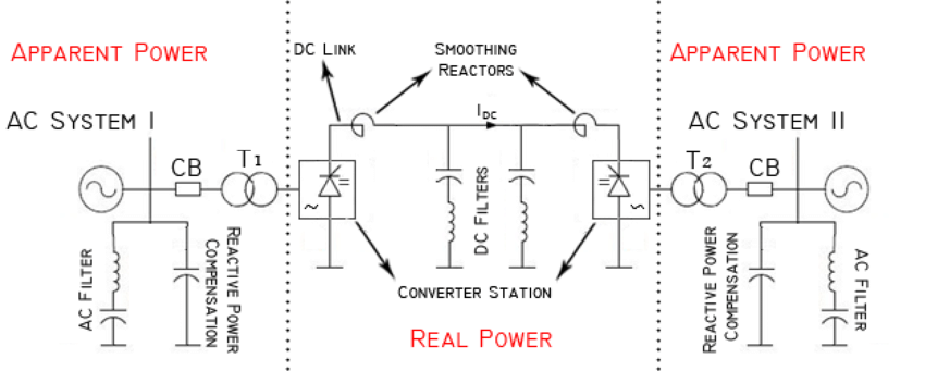
The special feature of the HVDC system is the DC circuit consisting of one 12- pulse 3- 3-phase converter in each valve hall. The converters of the valve halls are interconnected on the high-voltage side via smoothing reactors and DC overhead lines to the corresponding converters of the valve halls.
- Converter Stations:
- Rectifier Station: The rectifier station is located at the sending end of the HVDC system. It converts AC power from the AC grid into DC power for transmission. Key components of the rectifier station include:
- Thyristor valves or semiconductor devices that control the conversion process.
- Transformers to step down the AC voltage before rectification.
- Filters to reduce harmonics and ripple in the DC output.
- Inverter Station: The inverter station is located at the receiving end of the HVDC system. It converts the incoming DC power back into AC power suitable for distribution. Key components of the inverter station include:
- Inverter bridges or semiconductor devices that control the conversion process.
- Transformers to step up the AC voltage to grid-level voltage.
- Filters to smooth out the AC output.
- Rectifier Station: The rectifier station is located at the sending end of the HVDC system. It converts AC power from the AC grid into DC power for transmission. Key components of the rectifier station include:
- DC Transmission Lines: The DC transmission lines connect the rectifier and inverter stations. These lines typically consist of high-voltage cables or overhead lines designed for DC power transmission. They are insulated and designed to handle the high voltage and current associated with HVDC systems.
- Converter Transformers: These transformers are specialized transformers used in both the rectifier and inverter stations. They step voltage up or down as necessary and provide isolation between the AC grid and the HVDC equipment.
- Reactive Power Compensation Equipment: Reactive power control is crucial for grid stability. Capacitor banks or synchronous condensers are often used to provide or absorb reactive power as needed to maintain grid voltage stability.
- Control and Protection Systems: HVDC substations are equipped with sophisticated control and protection systems to monitor and manage the operation of the HVDC system. These systems include:
- Supervisory Control and Data Acquisition (SCADA) systems for remote monitoring and control.
- Protection relays to detect and respond to faults or abnormal conditions.
- Communication systems for data exchange between converter stations and grid operators.
- Grounding and Lightning Protection: Proper grounding and lightning protection measures are essential to ensure the safety of personnel and equipment in the substation.
- Switchgear and Circuit Breakers: Switchgear is used to control and isolate electrical equipment within the substation. Circuit breakers are installed to protect the system from overcurrent or faults.
- Auxiliary Systems: Various auxiliary systems, including cooling systems for the converter equipment, fire detection and suppression systems, and ventilation systems, are essential to maintain the substation’s operational integrity.
- HVDC Filters: These filters are used to suppress harmonics and transients in the HVDC system, ensuring the quality of the converted AC power.
- DC Switchyard (if applicable): In some HVDC systems, a DC switchyard may be used to connect multiple DC transmission lines or to facilitate maintenance and repairs.
- Control Building: Substations often have control buildings that house the control room, operator consoles, and other equipment for monitoring and controlling the HVDC system.
SUMMARY
These components work together to convert, transmit, and distribute electrical power efficiently and reliably over long distances using HVDC technology. The specific design and configuration of an HVDC substation can vary depending on factors such as the power rating, location, and project requirements.
