
A circuit breaker allows safe isolation and switching operations, reducing the risk of electrical hazards during normal and faulty electrical conditions. In this article, we will study the nameplate parameters of the SF6 circuit breaker.
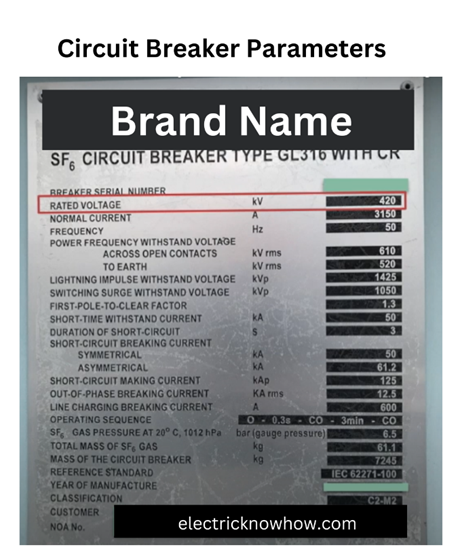
SF6 Circuit breakers facilitate the isolation of power transformers, EHT feeders, and busbars, ensuring the safe and efficient operation of substations. A fire arc is produced when the switching operation is carried out in a circuit breaker. As its name indicates SF6 stands for sulfur hexafluoride as it is used as an arc extinguisher medium in this circuit breaker. The nameplate details of an SF6 (sulfur hexafluoride) circuit breaker typically include essential information about the breaker’s specifications and ratings. Here’s what you might find on the nameplate:
International Standards
In most countries, these circuit breakers are manufactured according to international standards such as IEC (International Electro-technical Commission). All the parameters are according to the IEC-given standards. Some parameters are compulsory and some parameters depend on the manufacturers.
Here are two standards that must be followed:
- IEC 62271-100
- IEC 62271-1
Here is the list of IEC standards for high-voltage circuit breakers:
| Abbreviation | Unit | Circuit Breaker | Operating Device | Condition: Marking only required if | |
| 1 | 2 | 3 | 4 | 5 | 6 |
| Manufacturer | X | X | |||
| Type designation and serial number Rated voltage | X | X | |||
| Rated lightning impulses withstand voltage | Up | X | |||
| Rated Voltage | Ur | X | |||
| Rated switching impulse withstand voltage | Us | y | Rated 300kV and above | ||
| Rated frequency | fr | y | Rating is not applicable at both 50Hz & 60Hz | ||
| Rated normal current | X | ||||
| Rated duration of short circuit | y | Different from 1s | |||
| Rated short-circuit breaking current | X | ||||
| D.C. time constant of the rated short circuit breaking current | y | Different from 45ms | |||
| D.C. component of the rated short circuit breaking current at contact separation corresponding to the D.C. time constant of the rated short-circuit breaking current | y | ||||
| First pole-to-clear factor | y | Different from 1.3 for rated voltage 100kV to 170kV | |||
| Rated out-of-phase breaking current | (X) | ||||
| Rated line-charging breaking current | y | Rated voltage equal to or greater than 72.5kV | |||
| Rated single capacitor bank-breaking current | (X) | ||||
| Rated back-to-back capacitor bank breaking current | (X) | ||||
| Rated cable-charging breaking current | (X) | ||||
| Rated line-charging breaking current | (X) | ||||
| Rated single capacitor bank-breaking current | |||||
| Rated back-to-back capacitor bank breaking current | Ibr | ||||
| Rated back-to-back capacitor bank inrush making current | Iin | ||||
| Rated filling pressure for operation | Pfo | (X) | |||
| Rated filling pressure for interruption | Ppi | ||||
| Rated supply voltage of closing and opening devices | Usp | V | (X) | ||
| Rated supply frequency of closing and opening devices | Hz | (X) | |||
| Rated supply voltage of auxiliary circuits | Us | V | (X) | ||
| Rated supply frequency of auxiliary circuits | Hz | (X) |
Here is the representation of the above standards:
Marked with “X” = Compulsory parameters according to standards
Marked with “y” = It is based on the condition stated in column 6. For example, the highlighted parameter “y” in the table must be added on the nameplate of the circuit breaker from 300kV and above values. These parameters are decided by mutual understanding in between manufacturers and the client.
Marked with “(X)” = It is optional for the manufacturer.
Mandatory Parameters
Here are the following parameters that are a must for a manufacturer to mention:
- Manufacturer Name
- Designation and type of Circuit Breaker with its serial number
- Manufacturing year
- Relevant standard according to which a circuit breaker is manufactured
Other mandatory parameters are:
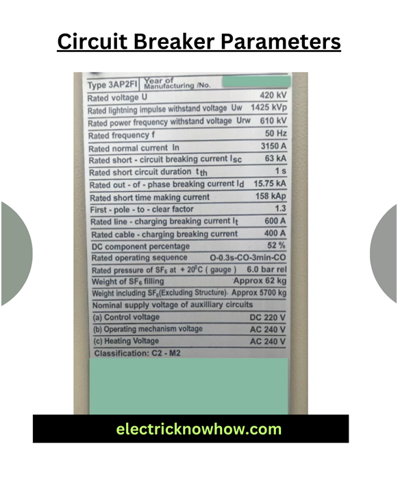
- Rated voltage (kV)
- Rated frequency (Hz)
- Rated normal current (A)
- Rated short circuit breaking current (KA)
- Rated duration of short circuit (sec)
- Rated peak withstand current or rated making current (kAp)
- Rated short-duration power frequency withstand voltage (kV) and rated lighting impulse withstand voltage (kVp)
- First pole to clear factor
- Rated operating sequence
- Rated pressure of SF6 gas (Bar / Mpa)
- Total weight of SF6 gas (kg)
- Total weight of CB (kg)
- Rated control voltage (V DC)
Now we will discuss the above parameters one by one:
1- Rated Voltages are the highest voltages for which a circuit breaker is designed for the “RMS” value of the phase-to-phase voltage of a three-phase system. Normal voltages are referred to as normal voltage present in the circuit breaker. For example, in the case of 420kV, 420kV are rated voltages and 400kV are normal voltages.
2- Frequency is the value at which power is generated or transmitted. It can be changed for different countries.
3- Rated current is the “RMS” value that a circuit breaker can carry continuously. These are the preferred value for the current:
- 400A
- 630A
- 800A
- 1250A
- 1600A
- 2000A
- 3150A
- 4000A
4- Rated short circuit breaking current (KA) is the maximum value of short circuit current breaking by a circuit breaker. It is also called a symmetrical breaking current. The symmetrical breaking current is the AC component of the short circuit current equal to the rated short circuit current and the asymmetrical breaking current is the combination of AC and DC components of short circuit current.
5- The rated duration of the short circuit (sec) is the time for which the circuit breaker can withstand with short circuit current. As per standard, it should be 3 sec or 1 sec.
6- If the circuit breaker closes during the existing fault, the current may increase to very high during the first cycle. In this condition, the breaker has to withstand that high current and its mechanical forces. It is 2.5 times of rated short circuit current. Its unit is in kA peak (for a very short time).
7- Rated short-duration power frequency withstand voltage (kV) and rated lighting impulse withstand voltage (kVp) are the highest system voltages used to check the insulation properties of equipment. It is also called insulation level if combined.
8- In the case of an AC circuit, currents are out of phase by 120°, and current interruption in the breaker is not simultaneous. Contact of one pole will open before the other two, and hence the power frequency recovery voltage across the first pole to open is more than the other. This is called the first pole to clear factor. It is given as times the normal system voltage. So, on the nameplate, you’ll find it is mentioned as 1.3. This means the first pole to open will have 1.3 times the normal system voltage across it, and the pole can sustain that.
9- Rated operating sequence is one of the important parameters of the breaker, it is also known as “Auto reclosing duty”.The operating sequence denotes the opening & closing operation breaker is capable of performing under specified conditions. As per IEC 62271-1 there are two alternatives for operating sequence,
Where,
O = Opening operation
C = closing operation
t,t’,t” = time intervals between successive
It means 90% of the faults on the system are transient, which remain in the system for a very short time and then the system goes back to normal.
10- The rated pressure of SF6 gas (Bar / Mpa) is the rated pressure of the SF6 gas in the breaker. It can be mentioned in bar or mega-pascals or in kg/ sq. cm. This will vary from manufacturer to manufacturer.
11- Total weight of SF6 gas (kg) also varies from manufacturer to manufacturer.
12- Rated control voltage (V DC) is the DC voltage on which the closing and tripping coil works.
There are other condition-based parameters of the circuit breaker including rated switching impulse to withstand voltage.
Summary
We have discussed the main parameters of the SF6 circuit breaker including compulsory and non-compulsory parameters. A manufacturer has to manufacture a circuit breaker according to international standards. These details are important for ensuring proper installation, operation, and maintenance of the SF6 circuit breaker. Always refer to the nameplate and accompanying documentation for accurate information specific to the particular unit.
