Close Menu
    Facebook X (Twitter) Instagram
    Trending
    • ⚡ Cable Types in Distribution: XLPE vs PILC vs Aerial Bundled Cables
    • ⚡ Smart Grid in Distribution: Role, Challenges & Indian Scenario
    • ⚡ Power Factor Correction in Distribution Systems
    • ⚡ Understanding Distribution Protection: Fuses, Relays & Reclosers
    • ⚡ Voltage Drop in Distribution Lines: Causes, Calculation & Correction
    • 🛠️ Distribution Transformer Maintenance: Checklist and Tips
    • INTRODUCTION TO SUBSTATION EARTHING
    • Maintenance of GIS (Gas-Insulated Switchgear)
    Electric Know How
    • Home
    • Generation
      • Hydropower Station
      • Thermal Power Station
      • DISTRIBUTED ENERGY SOURCES
      • Diesel Generator
      • Industrial Tools
      • DC System-Generating Stations
    • Transmission
      • High Voltage DC Transmission
      • High Voltage AC Transmission
        • Transmission line – An Overview
        • TRANSMISSION TOWER CONFIGURATION
        • Transmission Towers-Key Features
    • Distribution
      • ⚡ Understanding Electrical Distribution Systems: Basics to Architecture
      • ⚡ Top 5 Faults in Distribution Lines and How to Fix Them
      • 🛠️ Distribution Transformer Maintenance: Checklist and Tips
    • Protection
      • Power System Protection
        • Types of Fault in Power System
        • Relay Setting Calculation for Substation
        • Circuit Breaker
          • Nameplate details of SF6 Circuit Breaker
          • Major parameters of a circuit breaker
          • What is the use of an anti-pumping relay?
          • What is an IR Value Test in a Circuit Breaker? An overview
          • Testing of Circuit Breaker
        • Key Components of Control & Relay Panel
          • Relay Setting Calculation for Substation
          • Trip Circuit Supervision Relay
          • Three Phase Control Wiring
        • Switching Surges and Its Remedies
      • OVERVIEW OF TRANSFORMER PROTECTION
        • Differential Protection of Transformer
      • OVERVIEW OF GENERATOR PROTECTION
      • Distance Protection
      • Electrical Safety
    • Switchgear
      • Electrical Sub-Station
        • BATTERY SYSTEM IN GRID SUBSTATION
        • Operation of Float Cum Boost Charger
        • Protection Circuitry of Battery Charger
        • Power Transformer
          • INSULATION RESISTANCE OF TRANSFORMER
          • WTI AND OTI in Power Transformer
          • Transformer Oil Dielectric strength
          • On Load Tap Changing of Transformer
          • TRANSFORMER MAINTENANCE
        • Sub-Station Operation
        • Multiplying Factor for Energy Meter
      • Current Transformer
        • Nameplate Detail of Current Transformer – A Detail Guide
        • Current Transformer Knee Point Test – A Detailed Overview
        • What is a Current Transformer Polarity Test- Detailed Guide
        • Ratio test of Current Transformer
      • Potential Transformer
      • Isolator in Substation
        • Nameplate Detail of Isolators/Dis-connectors- A Detail Guide
      • Electrical Busbar
      • Insulators
      • Clamps and Connectors
      • Fire Fighting System
      • Lightening Arrester
        • LCM Test of a Lightning Arrestor – An Overview
      • Gas Insulated Substation
        • Local Control Cubicle
        • SF6 circuit breaker gas compartment
        • Maintenance of GIS (Gas-Insulated Switchgear)
    • Q&A
      • FAQS ON Current Transformer
      • POWER SYSTEM
      • FAQ ON BUSBAR
    Electric Know How
    Home»Generation»Operation of Float Cum Boost Charger
    Generation

    Operation of Float Cum Boost Charger

    madhusmitaBy madhusmita24 November 2022Updated:25 November 2022No Comments7 Mins Read
    Facebook Twitter Pinterest LinkedIn Tumblr Email
    Share
    Facebook Twitter LinkedIn Pinterest Email
    • DC voltage is most stable and reliable in nature for which the control and protection circuits in substations and power stations are designed to work on DC supply.
    • The DC voltage is obtained either from Battery Set or from the charger by the use of a rectifier unit (Conversion of AC supply to corresponding DC supply).
    • Maximum time DC voltage is obtained from Rectifier Unit Charger. But during emergency conditions like a failure of AC supply, maintenance/modification of charger unit, etc. to obtain the DC voltage, Battery Set is required. Moreover, it is also required for emergency lighting in the system, when there is a total failure of the AC supply.
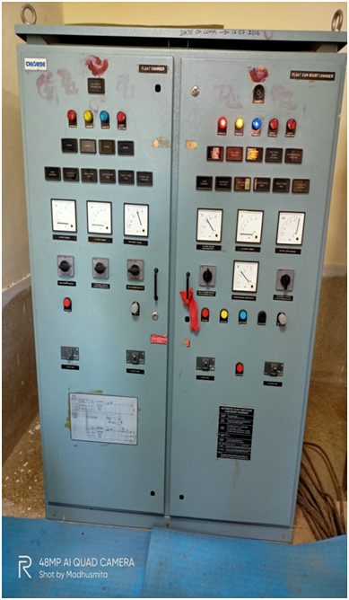
    • This is the front side and inside view of Float, cum boost charger panel used at 132/33KV air insulated substation control room.
    • A battery Charger, when used in the stand-by application is not a standalone dedicated Battery Charger. Here battery charger along with a floating battery provides an uninterrupted DC power supply to a critical load.
    • This is Float-cum-boost battery charger or FCBC feeds the critical load without any break and also charges the discharged battery.
    • Though FCBC denotes “Float-cum-Boost” which clearly means a single rectifier/converter for AC to DC conversion, for higher capacity or higher load “Float-and-Boost” charger is used which has two rectifiers, one for feeding load and another for charging the battery.
    • TECHNICAL SPECIFICATION OF AUTOMATIC FLOAT & FLOAT CUM BOOST BATTERY CHARGING EQUIPMENT SUITABLE FOR 220V 645AH PLANTE BATTERY
    • FLOAT CHARGER – SCR CONTROL:
    • Input Power Supply          –              415 Volts ±10%, 3-Phase, 4 Wire,50 Hz. ± 5%.
    • Output Voltage                                :                                
    •        Auto                                    –              247.5 Volts (2.25V/cell)
    •        Manual                                –              0V – 247.5 Volts.
    •                                                                                         
    • Output Current                      –  64 Amps DC continuous plus trickle charging current.                            
    • Output Ripple         –             Within 3% RMS at full load of  247.5 V DC
    •                                                                                                                            
    •  Output Regulation             –             Within ±1% for ±10% supply voltage fluctuation and 10-100% load variation.
    •   Mode of Operation          –              Automatic / Manual
    •   Control Configuration     –              3-Phase full wave full control thyristors bridge fed through the 3-phase transformer and controlled by constant potential controller unit with load limiting feature (AVR).

    Table of Contents

    Toggle
    • What is FCBC battery charger?
    • CHARGING PROCEDURE OF LEAD ACID BATTERY:
    • OPERATION OF BATTERY CHARGER

    What is FCBC battery charger?

    FCBC denotes “Float-cum-Boost” which clearly means a single rectifier/converter for AC to DC conversion, but for higher capacity or higher load “Float-and-Boost” charger is used which has two rectifiers, one for feeding load and another for charging the battery.

    CHARGING PROCEDURE OF LEAD ACID BATTERY:

    To keep a battery in healthy condition and to achieve optimum life of the battery, two modes of charging are required (i) Boost charging and (ii) Trickle/Float charging

    (i)Boost Charging:

    Boost charging means, the charging of a battery from discharged condition to a fully charged condition. In this mode, a constant current process is followed for efficient charging. During boost charging battery voltage varies from 1.85V/cell to 2.75V/cell. In between these, the point 2.35 V/cell is called the gassing point i.e. gassing starts at this point. Beyond this point, the charging current must be restricted to a certain limit, otherwise, that may damage the plates or may affect the life of the battery. Therefore, to charge a discharged battery efficiently, a two-step constant current process is the best process.

      (ii) Trickle / Float Charging:

    Trickle charging means, charging a battery at constant voltage to compensate for local discharge. For optimum trickle charging, the voltage should be maintained at 2.25V/cell. But for float operation, this voltage is restricted to 2.23V/cell.

    OPERATION OF BATTERY CHARGER

    The three-phase AC supply voltage is fed to a suitably rated step-down double-wound transformer through a suitably rated MCB. The secondary voltage of which is fed to a 3-Phase full wave full control thyristors bridge through line surge suppressor and semiconductor protection fuses. Thyristors of the bridge circuit are adequately protected by a snubber network as protection against voltage transients. The bridge circuit consists of 6 nos. of Thyristors.

    The triggering of the thyristors is controlled by the electronic voltage and/or current regulator unit, which senses feedback from both output voltage and current. These feedback signals are suitably processed and compared with the reference generated in the control circuit (Controlled by the electronic SCR control module). Then the error is amplified and phase compensated by the high gain operational amplifier. The output of the final amplifier is fed to the triggering circuit, which controls the output voltage and current of the charger by adjusting the firing angle of the thyristor. The incorporation of feedback ensures automatic correction of any deviation of the set voltage/current, which may arise due to line or load fluctuations.

    Share. Facebook Twitter Pinterest LinkedIn Tumblr Email
    Previous ArticleProtection Circuitry of Battery Charger
    Next Article Gas Insulated Substation
    madhusmita
    • Website
    • Facebook
    • Instagram
    • LinkedIn

    Related Posts

    TYPES OF EXCITATION SYSTEM

    23 December 2022

    Functions and Performance Requirements of Excitation Systems

    23 December 2022

    Thermal Power Station

    18 December 2022

    Comments are closed.

    Archives
    Categories
    • Distribution (15)
    • Generation (10)
    • Protection (24)
    • Q&A (7)
    • Switchgear (48)
      • Nameplate Details (2)
    • testing (11)
    • Transmission (20)
    Recent Posts
    • ⚡ Cable Types in Distribution: XLPE vs PILC vs Aerial Bundled Cables
    • ⚡ Smart Grid in Distribution: Role, Challenges & Indian Scenario
    • ⚡ Power Factor Correction in Distribution Systems
    • ⚡ Understanding Distribution Protection: Fuses, Relays & Reclosers
    • ⚡ Voltage Drop in Distribution Lines: Causes, Calculation & Correction
    Certification Course
    Electric Volt

    Quick Links

    • Home
    • About Us
    • Contact Us

    Post Categories

    • Generation
    • Transmission
    • Distribution
    • Protection
    • Switchgear
    • Q&A

    Vip Link

    • Privacy Policy
    • Disclaimer
    • Terms and Conditions

    Contact Us

    • ele.mamohanty@optcl.co.in
    Linkedin