This three-phase control wiring training course introduces basic safe operational aspects of electrical wiring in grid substations.
Step by Step Guide for Console box control wiring
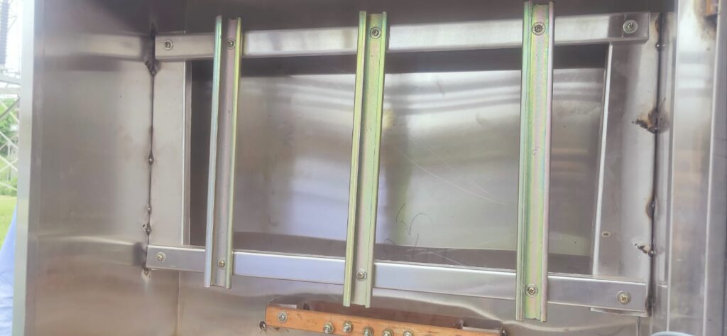
- Step-1 Fix the channels as per the width of Terminal blocks.
- Step-2 Fix the Terminal Blocks as per the requirement
- Step-3 Dressing the cable terminations.
- Step-4 Check for continuity of the cable
- Step-5 Start ferrule as per standards.
- Step-6 Insert the lugs and do the crimping properly
- Step-7 Tighten the lugs in the TB as per the connection diagram.
step-1

Step -2
There are two types of TB
- Stud Type
2. Disconnecting type
The disconnecting type TBs are here in the picture shown below.

Step 3
Cable Dressing & Terminations:
Cable terminations make physical and electrical connections between the cable and the terminal of the equipment, junction, or another cable, thereby facilitating the flow of electricity in the desired manner.
Cable terminations play an important role in the proper functioning of the cable and the equipment to which it is connected.
Cable dressing ensures that terminations are neatly arranged with the help of Cable ties, cable channels, and glands.
Step 4
Check the continuity of the cable with the help of a multimeter.
Step 5
Here for fixing the cable number and CRP (Control Relay Panel) box number ferrules are used. On this ferrule mark, the endpoints of cables is done that has to be installed between CRP to CT Console Box panel in AIS.

| Type | Description |
| Start Ferrule | The internal ferrules used in the CONTROLLING Equipment to be provided on both ends of the wire e.g. for remote controlling the CB the internal ferrule at the control panel to be used on the controlling wire |
| End ferrule | The internal ferrules used in the CONTROLLED Equipment to be provided on both ends of the wire e.g. for remote controlling the CB the internal ferrule at the BREAKER CUBICLE to be used on the controlling wire |
Ferrule System
Letters used in the Ferruling Scheme
| Letters | Purpose | Letters | Purpose |
| A | CT SEC Main Protection | L | Alarm, Indication, Annunciation circuit |
| B | Bus Bar Protection | M | Motor Control Circuit |
| C | Back up Protection | N | Transformer Tap Changer Control Circuit |
| D | CT Metering Circuit | P | Power Cable Identification |
| E | PT/CVT secondary circuit | Q | Equivalent Control Circuit |
| F | Fan Control Circuit | S | Event logger/DAS/SCADA circuit |
| G | PT Synchronising Circuit | T | Terminal Identification Circuit |
| H | LT AC Supply | U | Used for spare contacts |
| J | DC Main Circuit | X | Used for spare wires |
| K | DC Control Circuit |
FERRULING SCHEME
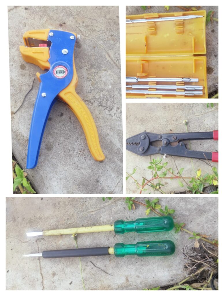
Step -6 Crimping Tool and other accessories for wiring
here one can see various tools required for console box wirings such as screwdrivers and crimping tools.

Step 7
The stud, washers, nuts, locknuts, and inserts shall be tin-plated Brass. Terminal block design shall include markings of terminals and the terminals shall be provided with transparent plastic, slip-on/clip-on terminal covers. Markings on the terminal strip shall correspond to the wire number and terminal numbers on the wiring
Wire colors for internal wiring
| Color of Wires | Purpose |
| RED | Phase connection is either directly connected to the primary circuit or secondary circuit of CT or PT |
| YELLOW | Phase connection is either directly connected to the primary circuit or secondary circuit of CT or PT |
| BLUE | Phase connection is either directly connected to the primary circuit or secondary circuit of CT or PT |
| BLACK | Star point connection of secondary circuit of CT and PT |
| GREEN | Connection to earth |
| GREY | Connection in DC Circuit |

