Close Menu
    Facebook X (Twitter) Instagram
    Trending
    • ⚡ Cable Types in Distribution: XLPE vs PILC vs Aerial Bundled Cables
    • ⚡ Smart Grid in Distribution: Role, Challenges & Indian Scenario
    • ⚡ Power Factor Correction in Distribution Systems
    • ⚡ Understanding Distribution Protection: Fuses, Relays & Reclosers
    • ⚡ Voltage Drop in Distribution Lines: Causes, Calculation & Correction
    • 🛠️ Distribution Transformer Maintenance: Checklist and Tips
    • INTRODUCTION TO SUBSTATION EARTHING
    • Maintenance of GIS (Gas-Insulated Switchgear)
    Electric Know How
    • Home
    • Generation
      • Hydropower Station
      • Thermal Power Station
      • DISTRIBUTED ENERGY SOURCES
      • Diesel Generator
      • Industrial Tools
      • DC System-Generating Stations
    • Transmission
      • High Voltage DC Transmission
      • High Voltage AC Transmission
        • Transmission line – An Overview
        • TRANSMISSION TOWER CONFIGURATION
        • Transmission Towers-Key Features
    • Distribution
      • ⚡ Understanding Electrical Distribution Systems: Basics to Architecture
      • ⚡ Top 5 Faults in Distribution Lines and How to Fix Them
      • 🛠️ Distribution Transformer Maintenance: Checklist and Tips
    • Protection
      • Power System Protection
        • Types of Fault in Power System
        • Relay Setting Calculation for Substation
        • Circuit Breaker
          • Nameplate details of SF6 Circuit Breaker
          • Major parameters of a circuit breaker
          • What is the use of an anti-pumping relay?
          • What is an IR Value Test in a Circuit Breaker? An overview
          • Testing of Circuit Breaker
        • Key Components of Control & Relay Panel
          • Relay Setting Calculation for Substation
          • Trip Circuit Supervision Relay
          • Three Phase Control Wiring
        • Switching Surges and Its Remedies
      • OVERVIEW OF TRANSFORMER PROTECTION
        • Differential Protection of Transformer
      • OVERVIEW OF GENERATOR PROTECTION
      • Distance Protection
      • Electrical Safety
    • Switchgear
      • Electrical Sub-Station
        • BATTERY SYSTEM IN GRID SUBSTATION
        • Operation of Float Cum Boost Charger
        • Protection Circuitry of Battery Charger
        • Power Transformer
          • INSULATION RESISTANCE OF TRANSFORMER
          • WTI AND OTI in Power Transformer
          • Transformer Oil Dielectric strength
          • On Load Tap Changing of Transformer
          • TRANSFORMER MAINTENANCE
        • Sub-Station Operation
        • Multiplying Factor for Energy Meter
      • Current Transformer
        • Nameplate Detail of Current Transformer – A Detail Guide
        • Current Transformer Knee Point Test – A Detailed Overview
        • What is a Current Transformer Polarity Test- Detailed Guide
        • Ratio test of Current Transformer
      • Potential Transformer
      • Isolator in Substation
        • Nameplate Detail of Isolators/Dis-connectors- A Detail Guide
      • Electrical Busbar
      • Insulators
      • Clamps and Connectors
      • Fire Fighting System
      • Lightening Arrester
        • LCM Test of a Lightning Arrestor – An Overview
      • Gas Insulated Substation
        • Local Control Cubicle
        • SF6 circuit breaker gas compartment
        • Maintenance of GIS (Gas-Insulated Switchgear)
    • Q&A
      • FAQS ON Current Transformer
      • POWER SYSTEM
      • FAQ ON BUSBAR
    Electric Know How
    Home»Protection»Trip Circuit Supervision Relay
    Protection

    Trip Circuit Supervision Relay

    madhusmitaBy madhusmita12 December 2022Updated:16 March 2023No Comments4 Mins Read
    Facebook Twitter Pinterest LinkedIn Tumblr Email
    Share
    Facebook Twitter LinkedIn Pinterest Email

    In case of a fault in our equipment or transmission line, we use different types of relays to issue a trip signal for that fault. Next, that relay is connected to its respective circuit breaker to separate the faulty portion from the healthy portion of the system. We will discuss the supervision of trip circuits in the article.

    Table of Contents

    Toggle
    • Introduction:
    • working
    • Practical Sensing Condition:

    Introduction:

    As the name shows the trip circuit remains under supervision by the trip circuit supervision relay. In industry, there are normally two circuits in circuit breakers. One is called closing and one is a tripping circuit. If the circuit breaker is not closed or not on during the fault and after the fault, we can check the circuit breaker to rectify the problem easily. But on the other hand, if the circuit breaker is not showing tripping during a fault, this is a panic condition. It means that the circuit breaker is not tripping during the fault condition. That fault may eventually cause fatal incidents of any kind in the power system. So this is quite important to trip the circuit breaker.

    The tripping circuit of the circuit breaker consists of the following equipment:

    • Auxiliary switches
    • Protection relays
    • Master trip relay
    • Relay auxiliary contacts

    These are responsible for affecting the efficiency of circuit breaker tripping during a fault.

    working

    We connect the trip circuit supervision relay with the trip circuit (wired). It implies that the trip relay monitors the trip circuit. The trip circuit relay injects a small magnitude of current into the tripping circuit. Normally its values lie between 3 to 4 mAmperes. This current passes through all the trip circuit and complete its path and then come back to the trip circuit relay. If the tripping circuit is healthy then all the injected current will come back into the trip circuit relay. In case of abnormality, the injected current is not the same when coming back to the trip circuit relay. In this condition, there is an alarm in the circuit breaker. This condition must be clarified in normal conditions instead of the fatal incident due to abnormality.

    Practical Sensing Condition:

    1. Now we are going to discuss some practical conditions that will be sensed by the trip circuit relay. If the tripping coil in the trip circuit relay goes open then in this case the trip circuit relay will consider it an abnormal condition and generate an alarm in your circuit. The tripping coil must be healthy. If the tripping coil opens, it means there will bea supply in the tripping coil but the coil will be energized so there will be no tripping of the circuit breaker.
    2. The tripping coil will sense the fault in the mechanism of the circuit breaker same as the tripping coil.
    3. If the supply of the tripping circuit is cut down, it’s also an abnormality condition so the tripping coil will again not be energized and the circuit breaker cannot open.

    Pre-monitoring system: 

    In this monitoring, the circuit breaker is in off condition. In this condition, the trip circuit relay performs its monitoring function continuously.

    Post-monitoring system: 

    In this monitoring when the circuit breaker is in on condition or in charged and running condition. In both conditions, there will be proper monitoring of the trip circuit.

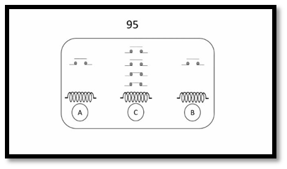
    This is showing the basic diagram of the trip circuit relay. Here is its representation number 95 . Coil A and Bare are for supervision and coil C is for indication. A coil work for the pre-closed condition of the breaker and Bworks for post closed condition of the circuit breaker.

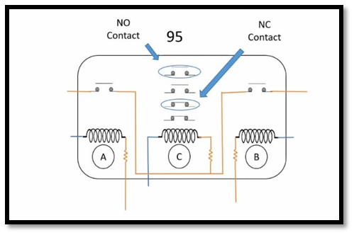
    Coil A and Coil Bare connected to a positive connection and then connected to Coil C. Here are pre-closed and post-closed supervision connections are also shown. Pre-closed supervision negative is in A coil and the post-closed supervision negative is in coil B. Normally open contact will be used in LED.

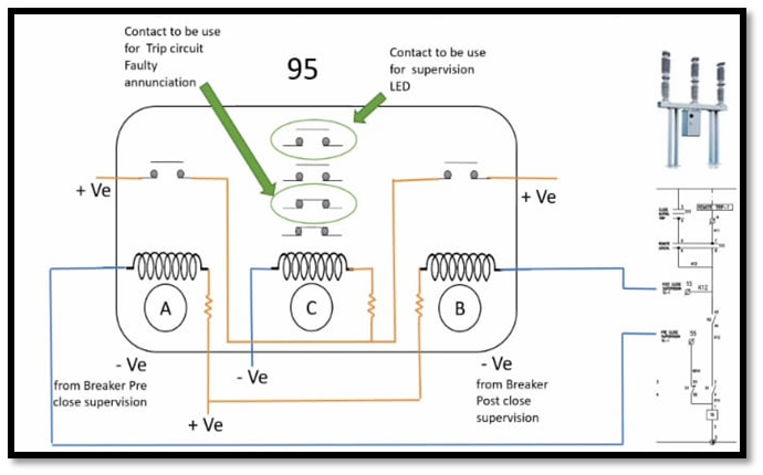
    C is the annunciation coil and one is the window connection means which coil from A or B is working.LED will be open when the connection will be in closed condition. When the trip coil is in healthy condition then Coil A and coil B will be operating and due to those coil C coil will also operate. C coil will close the topmost contact whenever it will be operating. Due to the closing of that switch LED will be on.

    Share. Facebook Twitter Pinterest LinkedIn Tumblr Email
    Previous ArticleDifferential Protection of Transformer
    Next Article Distance Protection
    madhusmita
    • Website
    • Facebook
    • Instagram
    • LinkedIn

    Related Posts

    ⚡ Understanding Distribution Protection: Fuses, Relays & Reclosers

    16 May 2025

    What is the use of an anti-pumping relay?

    22 July 2024

    Key Components of Control & Relay Panel

    25 May 2024

    Comments are closed.

    Archives
    Categories
    • Distribution (15)
    • Generation (10)
    • Protection (24)
    • Q&A (7)
    • Switchgear (48)
      • Nameplate Details (2)
    • testing (11)
    • Transmission (20)
    Recent Posts
    • ⚡ Cable Types in Distribution: XLPE vs PILC vs Aerial Bundled Cables
    • ⚡ Smart Grid in Distribution: Role, Challenges & Indian Scenario
    • ⚡ Power Factor Correction in Distribution Systems
    • ⚡ Understanding Distribution Protection: Fuses, Relays & Reclosers
    • ⚡ Voltage Drop in Distribution Lines: Causes, Calculation & Correction
    Certification Course
    Electric Volt

    Quick Links

    • Home
    • About Us
    • Contact Us

    Post Categories

    • Generation
    • Transmission
    • Distribution
    • Protection
    • Switchgear
    • Q&A

    Vip Link

    • Privacy Policy
    • Disclaimer
    • Terms and Conditions

    Contact Us

    • ele.mamohanty@optcl.co.in
    Linkedin