Close Menu
    Facebook X (Twitter) Instagram
    Trending
    • ⚡ Cable Types in Distribution: XLPE vs PILC vs Aerial Bundled Cables
    • ⚡ Smart Grid in Distribution: Role, Challenges & Indian Scenario
    • ⚡ Power Factor Correction in Distribution Systems
    • ⚡ Understanding Distribution Protection: Fuses, Relays & Reclosers
    • ⚡ Voltage Drop in Distribution Lines: Causes, Calculation & Correction
    • 🛠️ Distribution Transformer Maintenance: Checklist and Tips
    • INTRODUCTION TO SUBSTATION EARTHING
    • Maintenance of GIS (Gas-Insulated Switchgear)
    Electric Know How
    • Home
    • Generation
      • Hydropower Station
      • Thermal Power Station
      • DISTRIBUTED ENERGY SOURCES
      • Diesel Generator
      • Industrial Tools
      • DC System-Generating Stations
    • Transmission
      • High Voltage DC Transmission
      • High Voltage AC Transmission
        • Transmission line – An Overview
        • TRANSMISSION TOWER CONFIGURATION
        • Transmission Towers-Key Features
    • Distribution
      • ⚡ Understanding Electrical Distribution Systems: Basics to Architecture
      • ⚡ Top 5 Faults in Distribution Lines and How to Fix Them
      • 🛠️ Distribution Transformer Maintenance: Checklist and Tips
    • Protection
      • Power System Protection
        • Types of Fault in Power System
        • Relay Setting Calculation for Substation
        • Circuit Breaker
          • Nameplate details of SF6 Circuit Breaker
          • Major parameters of a circuit breaker
          • What is the use of an anti-pumping relay?
          • What is an IR Value Test in a Circuit Breaker? An overview
          • Testing of Circuit Breaker
        • Key Components of Control & Relay Panel
          • Relay Setting Calculation for Substation
          • Trip Circuit Supervision Relay
          • Three Phase Control Wiring
        • Switching Surges and Its Remedies
      • OVERVIEW OF TRANSFORMER PROTECTION
        • Differential Protection of Transformer
      • OVERVIEW OF GENERATOR PROTECTION
      • Distance Protection
      • Electrical Safety
    • Switchgear
      • Electrical Sub-Station
        • BATTERY SYSTEM IN GRID SUBSTATION
        • Operation of Float Cum Boost Charger
        • Protection Circuitry of Battery Charger
        • Power Transformer
          • INSULATION RESISTANCE OF TRANSFORMER
          • WTI AND OTI in Power Transformer
          • Transformer Oil Dielectric strength
          • On Load Tap Changing of Transformer
          • TRANSFORMER MAINTENANCE
        • Sub-Station Operation
        • Multiplying Factor for Energy Meter
      • Current Transformer
        • Nameplate Detail of Current Transformer – A Detail Guide
        • Current Transformer Knee Point Test – A Detailed Overview
        • What is a Current Transformer Polarity Test- Detailed Guide
        • Ratio test of Current Transformer
      • Potential Transformer
      • Isolator in Substation
        • Nameplate Detail of Isolators/Dis-connectors- A Detail Guide
      • Electrical Busbar
      • Insulators
      • Clamps and Connectors
      • Fire Fighting System
      • Lightening Arrester
        • LCM Test of a Lightning Arrestor – An Overview
      • Gas Insulated Substation
        • Local Control Cubicle
        • SF6 circuit breaker gas compartment
        • Maintenance of GIS (Gas-Insulated Switchgear)
    • Q&A
      • FAQS ON Current Transformer
      • POWER SYSTEM
      • FAQ ON BUSBAR
    Electric Know How
    Home»Protection»Key Components of Control & Relay Panel
    Protection

    Key Components of Control & Relay Panel

    madhusmitaBy madhusmita25 May 2024Updated:24 May 2025No Comments4 Mins Read
    Facebook Twitter Pinterest LinkedIn Tumblr Email
    Share
    Facebook Twitter LinkedIn Pinterest Email

    Table of Contents

    Toggle
    • INTRODUCTION
    • Terminal Blocks:
    • Auxiliary Contacts:
    • Power Source of Relays
    • SUMMARY

    INTRODUCTION

    In relay control and protection schematics, several key components are essential for ensuring proper operation and protection of electrical systems. Here’s an overview covering terminal blocks, auxiliary contacts, and relay power supply uses.
    In a control and relay (CR) panel, the wiring for facia and annunciator circuits, along with the implementation of protection schemes crucial for effective monitoring and control of electrical systems. Here’s an overview of how these components are typically integrated:

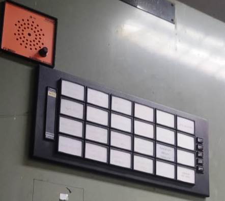
    1. Facia Circuit Wiring:
      • The facia circuit refers to the panel’s front-facing interface, which may include indicators, switches, meters, and other user interface elements.
      • Wiring for the facia circuit connects these interface elements to the control and monitoring devices within the CR panel.
      • This wiring ensures that operators can interact with the panel, monitor system parameters, and control various functions effectively.
      • For example, indicator lights may be wired to signal the status of different components or alarm conditions, while switches may be wired to control the operation of relays or other devices.
    2. Annunciation Circuit Wiring:
      • The annunciation circuit is responsible for providing visual or audible alarms to alert operators of abnormal conditions or faults within the electrical system.
      • Wiring for the annunciation circuit connects alarm devices such as buzzers, sirens, indicator lights, or annunciator panels to the monitoring and relay devices in the CR panel.
      • When a fault or abnormal condition is detected by the monitoring system, signals are sent to the annunciation circuit to activate the appropriate alarms.
      • Proper wiring and configuration of the annunciation circuit are essential for ensuring that operators are promptly alerted to potential issues, allowing them to take appropriate action to mitigate risks and prevent damage to equipment.
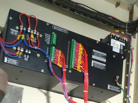
    Terminal Blocks:

    In schematics, terminal blocks are typically represented by rectangular boxes with labeled terminals or connection points. They are often used to connect power sources, relays, switches, sensors, and other devices.

    Proper labeling of terminal blocks is crucial for clarity and ease of understanding in schematics. Labels should indicate the function or purpose of each terminal, such as “L” for line, “N” for neutral, “COM” for common, and specific designations for input and output connections.
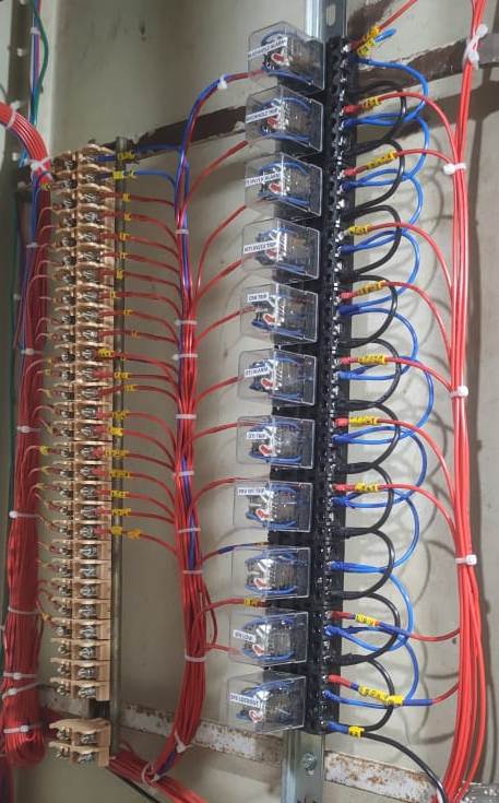
    oppo_0

    Auxiliary Contacts:

    In schematics, auxiliary contacts are depicted alongside the main relay symbol, usually with designated labels indicating their function and connection points. They are represented as smaller contact symbols connected to the main relay coil or contacts.

    Auxiliary contacts can be normally open (NO), normally closed (NC), or changeover contacts (CO), depending on their configuration and intended function. They play a crucial role in enhancing the functionality and flexibility of relay-based control and protection systems.

    Power Source of Relays

    Common sources of power for relays include:

    • AC (Alternating Current) mains power: Relays can be directly powered from the AC mains supply using appropriate voltage levels and connections. This method is commonly used in industrial and commercial applications where AC power is readily available.
    • DC (Direct Current) power supply: Relays can also be powered from a dedicated DC power source, which may be preferred in certain applications for compatibility with DC control circuits or where AC power is not available or practical.
    • External power supply units: In some cases, external power supply units or transformers may be used to provide the required voltage and current levels for relay operation. These units are typically integrated into the overall system design to ensure a reliable and stable power supply to the relays.

    SUMMARY

    In schematics, the power supply connections for relays are typically indicated by labeled lines or symbols representing the power source and connections to the relay coils. Proper power supply design and wiring are essential to ensure the reliable and consistent operation of relay-based control and protection systems.

    ElectricKnowHow Editorial
    Empowering Electrical Knowledge

    transmission
    Share. Facebook Twitter Pinterest LinkedIn Tumblr Email
    Previous ArticleTRANSMISSION TOWER CONFIGURATION
    Next Article What is the use of an anti-pumping relay?
    madhusmita
    • Website
    • Facebook
    • Instagram
    • LinkedIn

    Related Posts

    ⚡ Smart Grid in Distribution: Role, Challenges & Indian Scenario

    16 May 2025

    ⚡ Power Factor Correction in Distribution Systems

    16 May 2025

    ⚡ Understanding Distribution Protection: Fuses, Relays & Reclosers

    16 May 2025

    Comments are closed.

    Archives
    Categories
    • Distribution (15)
    • Generation (10)
    • Protection (24)
    • Q&A (7)
    • Switchgear (48)
      • Nameplate Details (2)
    • testing (11)
    • Transmission (20)
    Recent Posts
    • ⚡ Cable Types in Distribution: XLPE vs PILC vs Aerial Bundled Cables
    • ⚡ Smart Grid in Distribution: Role, Challenges & Indian Scenario
    • ⚡ Power Factor Correction in Distribution Systems
    • ⚡ Understanding Distribution Protection: Fuses, Relays & Reclosers
    • ⚡ Voltage Drop in Distribution Lines: Causes, Calculation & Correction
    Certification Course
    Electric Volt

    Quick Links

    • Home
    • About Us
    • Contact Us

    Post Categories

    • Generation
    • Transmission
    • Distribution
    • Protection
    • Switchgear
    • Q&A

    Vip Link

    • Privacy Policy
    • Disclaimer
    • Terms and Conditions

    Contact Us

    • ele.mamohanty@optcl.co.in
    Linkedin