Facebook Twitter Instagram
    Trending
    • Testing of Circuit Breaker
    • Faults in Distribution Lines
    • Distribution System Overview
    • Transmission Towers
    • TRANSFORMER MAINTENANCE
    • OVERVIEW OF GENERATOR PROTECTION
    • TYPES OF EXCITATION SYSTEM
    • Functions and Performance Requirements of Excitation Systems
    Learn With Electric Know How
    • Home
    • Generation
      • Hydropower Station
      • Thermal Power Station
      • DISTRIBUTED ENERGY SOURCES
      • Diesel Generator
      • Industrial Tools
      • DC System-Generating Stations
    • Transmission
      • High Voltage DC Transmission
      • High Voltage AC Transmission
      • Three Phase Control Wiring
    • Distribution
      • Distribution System Overview
      • Faults in Distribution Lines
    • Protection
      • Power System Protection
        • Types of Fault in Power System
        • Circuit Breaker
      • OVERVIEW OF TRANSFORMER PROTECTION
        • Differential Protection of Transformer
      • OVERVIEW OF GENERATOR PROTECTION
      • Distance Protection
      • Electrical Safety
    • Switchgear
      • Electrical Sub-Station
        • BATTERY SYSTEM IN GRID SUBSTATION
        • Operation of Float Cum Boost Charger
        • Protection Circuitry of Battery Charger
        • Transformer
          • INSULATION RESISTANCE OF TRANSFORMER
          • WTI AND OTI in Power Transformer
          • Transformer Oil Dielectric strength
        • Sub-Station Operation
        • Multiplying Factor for Energy Meter
      • Current Transformer
      • Potential Transformer
      • Isolator in Substation
      • Electrical Busbar
      • Insulators
      • Clamps and Connectors
      • Fire Fighting System
      • Lightening Arrester
      • Gas Insulated Substation
        • Local Control Cubicle
        • SF6 circuit breaker gas compartment
    • Q&A
      • FAQS ON CT
      • POWER SYSTEM
      • FAQ ON BUSBAR
    Learn With Electric Know How
    Home»Generation»Three Phase Control Wiring
    Generation

    Three Phase Control Wiring

    madhusmitaBy madhusmitaNovember 25, 2022Updated:March 16, 2023No Comments3 Mins Read
    Facebook Twitter Pinterest LinkedIn Tumblr Email
    Share
    Facebook Twitter LinkedIn Pinterest Email

    This three-phase control wiring training course introduces basic safe operational aspects of electrical wiring in grid substations.

    Step by Step Guide for Console box control wiring

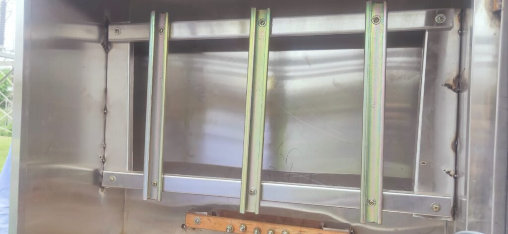
    • Step-1 Fix the channels as per the width of Terminal blocks.
    • Step-2 Fix the Terminal Blocks as per the requirement
    • Step-3 Dressing the cable terminations.
    • Step-4 Check for continuity of the cable
    • Step-5 Start ferrule as per standards.
    • Step-6 Insert the lugs and do the crimping properly
    • Step-7 Tighten the lugs in the TB as per the connection diagram.

    step-1

    Step -2

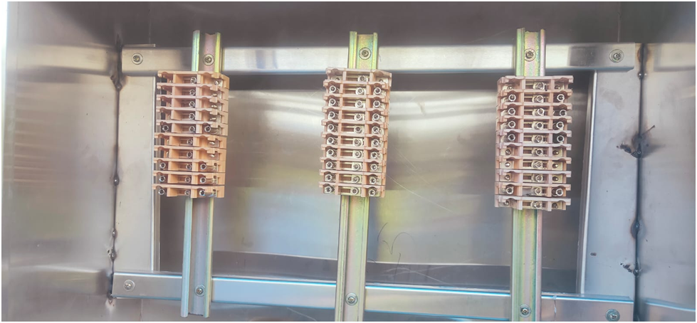
    There are two types of TB

    1. Stud Type

    2. Disconnecting type

    The disconnecting type TBs are here in the picture shown below.

    Step 3

    Cable Dressing & Terminations:

    Cable terminations make physical and electrical connections between the cable and the terminal of the equipment, junction, or another cable, thereby facilitating the flow of electricity in the desired manner.

    Cable terminations play an important role in the proper functioning of the cable and the equipment to which it is connected.

    Cable dressing ensures that terminations are neatly arranged with the help of  Cable ties, cable channels, and glands.

    Step 4

    Check the continuity of the cable with the help of a multimeter.
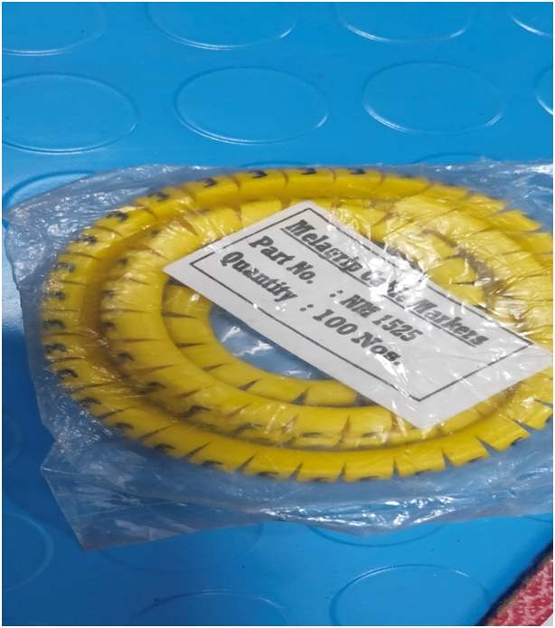
    Step 5

    Here for fixing the cable number and CRP (Control Relay Panel) box number ferrules are used. On this ferrule mark, the endpoints of cables is done that has to be installed between CRP to CT Console Box panel in AIS.

    TypeDescription
    Start FerruleThe internal ferrules used in the CONTROLLING Equipment to be provided on both ends of the wire e.g. for remote controlling the CB the internal ferrule at the control panel to be used on the controlling wire
    End ferruleThe internal ferrules used in the CONTROLLED Equipment to be provided on both ends of the wire e.g. for remote controlling the CB the internal ferrule at the BREAKER CUBICLE to be used on the controlling wire

    Ferrule System

    Letters used in the Ferruling Scheme

    LettersPurposeLettersPurpose
    ACT SEC Main ProtectionLAlarm, Indication, Annunciation circuit
    BBus Bar ProtectionMMotor Control Circuit
    CBack up ProtectionNTransformer Tap Changer Control Circuit
    DCT Metering CircuitPPower Cable Identification
    EPT/CVT secondary circuitQEquivalent Control Circuit
    FFan Control CircuitSEvent logger/DAS/SCADA circuit
    GPT Synchronising CircuitTTerminal Identification Circuit
    HLT AC SupplyUUsed for spare contacts
    JDC Main CircuitXUsed for spare wires
    KDC Control Circuit

    FERRULING SCHEME

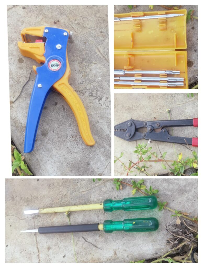
    Step -6 Crimping Tool and other accessories for wiring

    here one can see various tools required for console box wirings such as screwdrivers and crimping tools.

    Step 7

    The stud, washers, nuts, locknuts, and inserts shall be tin-plated Brass. Terminal block design shall include markings of terminals and the terminals shall be provided with transparent plastic, slip-on/clip-on terminal covers. Markings on the terminal strip shall correspond to the wire number and terminal numbers on the wiring

    Wire colors for internal wiring

    Color of WiresPurpose
    REDPhase connection is either directly connected to the primary circuit or secondary circuit of CT or PT
    YELLOWPhase connection is either directly connected to the primary circuit or secondary circuit of CT or PT
    BLUEPhase connection is either directly connected to the primary circuit or secondary circuit of CT or PT
    BLACKStar point connection of secondary circuit of CT and PT
    GREENConnection to earth
    GREYConnection in DC Circuit

    WIRE COLORS FOR INTERNAL WIRING

    Share. Facebook Twitter Pinterest LinkedIn Tumblr Email
    Previous ArticleCurrent Transformer
    Next Article FAQS ON CT
    madhusmita
    • Website
    • Facebook
    • Instagram
    • LinkedIn

    Related Posts

    TYPES OF EXCITATION SYSTEM

    December 23, 2022

    Functions and Performance Requirements of Excitation Systems

    December 23, 2022

    Thermal Power Station

    December 18, 2022

    Comments are closed.

    Recent Posts
    • Testing of Circuit Breaker
    • Faults in Distribution Lines
    • Distribution System Overview
    • Transmission Towers
    • TRANSFORMER MAINTENANCE
    Recent Comments
    • Faults in Distribution Lines - Learn With Electric Know How on Distribution System Overview
    • POWER SYSTEM - Learn With Electric Know How on Distribution System Overview
    • POWER SYSTEM - Learn With Electric Know How on Thermal Power Station
    • Basics of Power System Protection - Learn With Electric Know How on OVERVIEW OF GENERATOR PROTECTION
    • Functions and Performance Requirements of Excitation Systems - Learn With Electric Know How on TYPES OF EXCITATION SYSTEM
    Archives
    • March 2023
    • December 2022
    • November 2022
    Categories
    • Distribution
    • Generation
    • Protection
    • Q&A
    • Switchgear
    • Transmission
    • Uncategorized
    Meta
    • Register
    • Log in
    • Entries feed
    • Comments feed
    • WordPress.org

    Quick Links

    • Home
    • About Us
    • Contact Us

    Post Categories

    • Generation
    • Transmission
    • Distribution
    • Protection
    • Switchgear
    • Q&A

    Vip Link

    • Privacy Policy
    • Disclaimer
    • Terms and Conditions

    Contact Us

    • [email protected]
    Youtube Linkedin