
In this article, we will discuss the block diagram of the Battery Charger along with the battery set and the different types of annunciation and protection circuitry of the Float Cum Boost Charger. Next, we will discuss various control cards and troubleshooting components of the charger.
BLOCK DIAGRAM OF CHARGER + BATTERY SET
BASIC FUNCTION OF BATTERY CHARGER:– A.C. Voltage is converted to D.C. Voltage by means of rectifier units.
Characteristics:-
1. Provides constant DC voltage to OUTPUT LOADS.
2. Used with Filters to avoid ripples and harmonics
3. Simultaneous charging of Battery system and supply voltage to Load
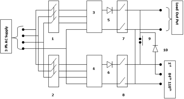
- MCCB FOR FLOAT CHARGER.
2. MCCB FOR BOOST CHARGER
3. TRANSFORMER RECTIFIER MODULE (FLOAT)
4. TRANSFORMER RECTIFIER MODULE (BOOST)
5. BLOCKER DIODE (FLOAT)
6. BLOCKER DIODE (BOOST)
7. OUTPUT MCCB FOR FLOAT CHARGER.
8. OUTPUT MCCB FOR BOOST CHARGER.
9. DC CONTACTOR (DC1)
10.BLOCKER DIODE (BD3)
The function of Tap Cell Connection
It plays the role during the “BOOST CHARGE” mode of the charger. During this condition, the battery voltage becomes as high as 2.6 V/cell at a higher charging current. So, to avoid high voltage connection (2.6×110= 286 V) to the load, the tap cell connection facility is provided in the charger system. Due to this arrangement reduced voltage (2.6×84 = 218 V) becomes available across the load circuit.
ANNUNCIATION AND PROTECTION SCHEME
1. AC SUPPLY TROUBLE RELAY (ACSTR)
2. CHARGER OVER CURRENT RELAY
3. FUSE FAIL MODULES.
4. INTEGRATED DC SENSING RELAY MODULE (IDSR)
A.DC UNDER/OVER VOLTAGE RELAY
B.BATTERY EARTH FAULT RELAY
C.CHARGER FAIL RELAY
D.START / FINISH RELAY
E.FLOAT / BOOST CHANGEOVER RELAY
F.BATTERY UNDER VOLTAGE RELAYS
Control Cards in Battery Charger
1. Power Supply Card:
The main function of this card is to provide the supply to other different cards in the system. Generally, a single-phase AC supply becomes the input for this card, and output is extended in the form of either DC or reduced AC to other available cards in the circuit. The testing points are also provided to trace the fault during the troubleshooting of the card
2. SCR Control card:
The main function of this card is to provide a suitable firing angle to the available 3 Phase supply for the development of a unified DC supply system. So this card contains three different control circuits for the control of the supply system. Fundamentally each circuit contains a diode and a suitable Zener diode for clamping the rectified wave in the circuit.

Gate Firing Logic Circuit (GFLC)
3. Amplifier Control Card: This card compares the feedback voltage/current signals with the reference and amplifies the error. The mili-volt signal from the shunt circuit is very weak for use in the system and needs amplification. These cards by the fundamental use of OPAMP amplify a larger voltage/current signal for purpose of the use in the circuit.
4. Current Limiting Control Card: This card is used to indicate the operation of the current limit in the system, which operates in conjunction with the amplifier card and device signal from the defined GATE circuit.
5. Pulse Control Card: The main function of this card is to isolate the power circuit and control circuit. The voltage level of the control circuit is less and needs to be isolated from the power circuit from the probable high voltage supply.
6. Protection Control Card: For the case of any abnormality like a short circuit, earth fault, over-voltage, etc.. in the system, this card actuates the signal to prevent the firing from the SCR control card and in turn causes the outage of the system from the supply. Then after correction of the fault and resetting the system the charger can be made on and can be taken to the circuit.
Rectification of Battery Charger
| Sl No | Faults/problems | Probable fault condition | Rectification |
| 1 | No DC Output | 1. Fuse might be blown or loose connection 2. Transformer may be faulty 3. Contactor/Relay might be faulty 4. Problem in the Control Cards. | 1. Replace the fuse after checking the input and output terminal of the fuse system by test lamp. 2. Replace/ repair the system 3. Replace the component 4. Check the test terminals of the card or replace the same. |
| 2 | Drooping of DC voltage on Loading | 1. Blowing out of the Rectifier system or the fuse connected in the circuit 2. Problem in the control card | 1. Replace the faulty rectifier or the blown-out fuse Check the test terminals of the card or replace the same |
| 3 | Ripple and disturbed output | 1. Rectifier or filter circuit fuse be blown 2. Control Rectifier (SCR) might be faulty. 3. Capacitor might be weak 4. Pot setting might be disturbed in the control card. | 1. Replace the blown fuse 2. Replace the faulty SCR 3. Test the capacitor and replace it accordingly 4. Adjust the setting and test the output or replace the card. |
| 4 | AUTO MODE output problem | 1. Problem in the output circuitry 2. Control card problem i.e over adjustment of the system | 1. Check the circuitry and rectify 2. Replace the card |
