Facebook Twitter Instagram
    Trending
    • Testing of Circuit Breaker
    • Faults in Distribution Lines
    • Distribution System Overview
    • Transmission Towers
    • TRANSFORMER MAINTENANCE
    • OVERVIEW OF GENERATOR PROTECTION
    • TYPES OF EXCITATION SYSTEM
    • Functions and Performance Requirements of Excitation Systems
    Learn With Electric Know How
    • Home
    • Generation
      • Hydropower Station
      • Thermal Power Station
      • DISTRIBUTED ENERGY SOURCES
      • Diesel Generator
      • Industrial Tools
      • DC System-Generating Stations
    • Transmission
      • High Voltage DC Transmission
      • High Voltage AC Transmission
      • Three Phase Control Wiring
    • Distribution
      • Distribution System Overview
      • Faults in Distribution Lines
    • Protection
      • Power System Protection
        • Types of Fault in Power System
        • Circuit Breaker
      • OVERVIEW OF TRANSFORMER PROTECTION
        • Differential Protection of Transformer
      • OVERVIEW OF GENERATOR PROTECTION
      • Distance Protection
      • Electrical Safety
    • Switchgear
      • Electrical Sub-Station
        • BATTERY SYSTEM IN GRID SUBSTATION
        • Operation of Float Cum Boost Charger
        • Protection Circuitry of Battery Charger
        • Transformer
          • INSULATION RESISTANCE OF TRANSFORMER
          • WTI AND OTI in Power Transformer
          • Transformer Oil Dielectric strength
        • Sub-Station Operation
        • Multiplying Factor for Energy Meter
      • Current Transformer
      • Potential Transformer
      • Isolator in Substation
      • Electrical Busbar
      • Insulators
      • Clamps and Connectors
      • Fire Fighting System
      • Lightening Arrester
      • Gas Insulated Substation
        • Local Control Cubicle
        • SF6 circuit breaker gas compartment
    • Q&A
      • FAQS ON CT
      • POWER SYSTEM
      • FAQ ON BUSBAR
    Learn With Electric Know How
    Home»Transmission»Potential Transformer
    Transmission

    Potential Transformer

    madhusmitaBy madhusmitaNovember 25, 2022Updated:November 25, 2022No Comments4 Mins Read
    Facebook Twitter Pinterest LinkedIn Tumblr Email
    Share
    Facebook Twitter LinkedIn Pinterest Email

    This electrical Potential Transformer(PT) training course introduces basic safe operational and field diagnostics of PTs with a focus on safe operation, testing, and maintenance of the PTs normally installed in substations.

    Why do we need a potential transformer?

    In order to decrease the transmission losses, after the generation of power, we step-up the voltage value in order to transmit it to a long distance. At receiving end, we again step down the voltage value and use it for our load.

    Voltages in transmission lines can go up to 765kV and if we try to measure it directly on the transmission line, our instrument insulation, according to large voltage, is huge. Similarly, our measuring instrument size and cost will also be increased. This is the disadvantage of measuring direct voltages on the transmission lines. Moreover, it is not safe for the person or worker on the line.

    So, we will step down the value in order to measure it easily. The size and cost of measuring instruments will be decreased. Second, we will provide proper isolation to such a high value of voltages. So, we will isolate the meter from our supply. So, we will use a transformer because it will transmit the power from primary to secondary. Secondary standard voltages are 110V with respect to the primary side. In order to get the desired secondary voltage values, we will design the N1 (Primary) and N2 (Secondary) turn ratios accordingly.

    In this way, we will get two benefits:

    • Isolation
    • Step-down voltage values

    Parts of Potential Transformer

    Like power transformers we have different parts of potential transformers:

    In the below diagram, you can see multiple parts of the potential transformer.
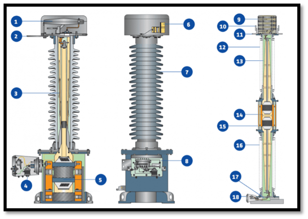
    1-Expansion Bellow

    2-Primary terminal

    3-Bushing

    4-Secondary terminal Box

    5-Core assembly

    6-Oil level indication

    7-Insulator

    8-Secondary terminal Box

    9-Expansion Bellow( To absorb thermal heat)

    10-Lifting eye

    11-Primary terminal

    12-Post type insulator

    13-Bushing

    14-2 Coils and assembly

    15-Transformer Tank

    16-Insulator

    17-Air to oil seal Bock (Like a vessel or tank)

    18-Secondary box

    Difference between power and potential transformers:

    Power transformers are designed in keeping view that it works for maximum efficiency, voltage regulation must be minimum and our overall cost must be less. Temperature rise will decide its rating value. But the potential is just an instrument transformer connected to a voltmeter. The power consumed by this transformer is quite less because the load does not consume the power. Our main concern is that primary voltage must be actually transferred to secondary according to its rating. There should be no angle difference between the primary and secondary sides.

    Construction of Potential Transformer:

    For its construction, we use a high-quality core with less flux density. We intend to make a small magnetizing current so we want to drop the error of the transformer. The design of the transformer is made to reduce the phase shift and voltage variation with the load. As we know it is a step-down transformer so we number of primary turns are less than the secondary.

    We try to use the hard type of fiber in order to separate the coil. Then we try to design winding in such a way that it reduces leakage reactance.

    Connection:

    The potential transformer is connected in parallel in the main circuit. The voltmeter or wattmeter is connected in its secondary while the Power line goes in its primary side. As we have low voltage so we can measure it by using a simple meter.

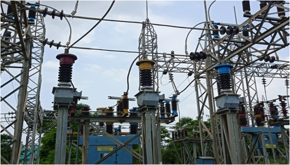
    33KV POTENTIAL TRANSFORMER

    Application:

    They are used for multiple purposes:

    • Monitoring high loads
    • Measuring high values of voltages
    • Generator and feeder synchronization
    • Protection Purposes
    • Used in high power lines communication networks.

    Share. Facebook Twitter Pinterest LinkedIn Tumblr Email
    Previous ArticleCircuit Breaker
    Next Article Current Transformer
    madhusmita
    • Website
    • Facebook
    • Instagram
    • LinkedIn

    Related Posts

    INSULATION RESISTANCE OF TRANSFORMER

    November 25, 2022

    WTI AND OTI in Power Transformer

    November 25, 2022

    Transformer

    November 25, 2022

    Comments are closed.

    Recent Posts
    • Testing of Circuit Breaker
    • Faults in Distribution Lines
    • Distribution System Overview
    • Transmission Towers
    • TRANSFORMER MAINTENANCE
    Recent Comments
    • Faults in Distribution Lines - Learn With Electric Know How on Distribution System Overview
    • POWER SYSTEM - Learn With Electric Know How on Distribution System Overview
    • POWER SYSTEM - Learn With Electric Know How on Thermal Power Station
    • Basics of Power System Protection - Learn With Electric Know How on OVERVIEW OF GENERATOR PROTECTION
    • Functions and Performance Requirements of Excitation Systems - Learn With Electric Know How on TYPES OF EXCITATION SYSTEM
    Archives
    • March 2023
    • December 2022
    • November 2022
    Categories
    • Distribution
    • Generation
    • Protection
    • Q&A
    • Switchgear
    • Transmission
    • Uncategorized
    Meta
    • Register
    • Log in
    • Entries feed
    • Comments feed
    • WordPress.org

    Quick Links

    • Home
    • About Us
    • Contact Us

    Post Categories

    • Generation
    • Transmission
    • Distribution
    • Protection
    • Switchgear
    • Q&A

    Vip Link

    • Privacy Policy
    • Disclaimer
    • Terms and Conditions

    Contact Us

    • [email protected]
    Youtube Linkedin