Facebook Twitter Instagram
    Trending
    • Testing of Circuit Breaker
    • Faults in Distribution Lines
    • Distribution System Overview
    • Transmission Towers
    • TRANSFORMER MAINTENANCE
    • OVERVIEW OF GENERATOR PROTECTION
    • TYPES OF EXCITATION SYSTEM
    • Functions and Performance Requirements of Excitation Systems
    Learn With Electric Know How
    • Home
    • Generation
      • Hydropower Station
      • Thermal Power Station
      • DISTRIBUTED ENERGY SOURCES
      • Diesel Generator
      • Industrial Tools
      • DC System-Generating Stations
    • Transmission
      • High Voltage DC Transmission
      • High Voltage AC Transmission
      • Three Phase Control Wiring
    • Distribution
      • Distribution System Overview
      • Faults in Distribution Lines
    • Protection
      • Power System Protection
        • Types of Fault in Power System
        • Circuit Breaker
      • OVERVIEW OF TRANSFORMER PROTECTION
        • Differential Protection of Transformer
      • OVERVIEW OF GENERATOR PROTECTION
      • Distance Protection
      • Electrical Safety
    • Switchgear
      • Electrical Sub-Station
        • BATTERY SYSTEM IN GRID SUBSTATION
        • Operation of Float Cum Boost Charger
        • Protection Circuitry of Battery Charger
        • Transformer
          • INSULATION RESISTANCE OF TRANSFORMER
          • WTI AND OTI in Power Transformer
          • Transformer Oil Dielectric strength
        • Sub-Station Operation
        • Multiplying Factor for Energy Meter
      • Current Transformer
      • Potential Transformer
      • Isolator in Substation
      • Electrical Busbar
      • Insulators
      • Clamps and Connectors
      • Fire Fighting System
      • Lightening Arrester
      • Gas Insulated Substation
        • Local Control Cubicle
        • SF6 circuit breaker gas compartment
    • Q&A
      • FAQS ON CT
      • POWER SYSTEM
      • FAQ ON BUSBAR
    Learn With Electric Know How
    Home»Protection»Differential Protection of Transformer
    Protection

    Differential Protection of Transformer

    madhusmitaBy madhusmitaNovember 29, 2022Updated:December 24, 2022No Comments4 Mins Read
    Facebook Twitter Pinterest LinkedIn Tumblr Email
    Share
    Facebook Twitter LinkedIn Pinterest Email

    We need the protection of equipment as well as we need safety measures for transmission or distribution line systems. Basically, there are fewer chances of a fault occurring in static devices such as transformers yet we need to protect them from those faults.

    Introduction:

    In induction motors or in alternators there are more faults but in transformers, we face fewer faults as the transformer is a static device. But any problem in the transformer causes a huge loss in the power system as the transformer plays an important role in power distribution by stepping down the incoming voltages. So we have some methods or techniques to cover faults in transformers.

    Differential Relay:

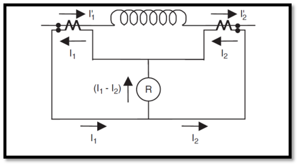
    It will operate for the same quantities like the same voltages or the same current values and from exceeding the value of their pre-fixed values relay will operate. For example, we have an electric coil and if the same current flows through the entering and leaving ends of the coil, the relay will not operate. This is the normal condition of the relay. It will only operate with a difference of these values.

    We have over current relay, alternating winding of the transformer, and two CTs (Current Transformer) to step the current value for the relay using a specific CT ratio. The same current is flowing through the circuit and that is called the circulating current.  In fault conditions flowing current will not flow be the same on both sides but there will be differences in their values. That difference in values will energize the relay coil and it will separate the faulty portion from the healthy portion by tripping the main circuit.

    We all know that there are two sides of a power transformer; primary and secondary that may connect in a star-delta or delta-delta or delta-star connection. We have current transformers with circuit breakers and a relay is also present there.

    Effect of Tap Changing

    As in tap changing, we change the turn ratio which will change the value of the voltage on the primary and secondary sides. By changing the voltage ratio current will also be changed. Due to this difference current will flow through the relay and it will trip. So, to avoid tap changing fault we use a percentage differential relay.

    Effect of Inrush Current

    At the start, there is magnetizing current flow through a transformer. It is normally 6-8% of load current which means it is a high value. But generally, it does not deteriorate our transformer. But the relay will trip the circuit yet this current is for short time.

    We can add a time delay but generally, it is not practicable as during delay time fault current may occur and that can damage the circuit.

    Practical concept of differential relay:

    Let’s have a practical example in which we have a differential relay for the transformer. We have these relays on the high and low-voltage sides of the transformer and on both sides, we have CTs to measure the current.

    You can see this in the images below mentioned:

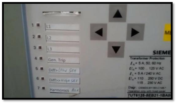
    We have two values from CTs of both sides of the transformer. Both CTs have a set point on which their difference is fixed and when there comes a difference from their set value in case of any fault, the transformer will trip.

    There is a different indication of different values on which the relay will trip. L1, L2, and L3 are phase-tripping indications from any of the three phases. Gen tripping indication is for any general relay tripping. For the low side of the transformer low side indication will be on. For example, in the case of a 132/11kV transformer, the low side is 1kV. Similarly, 132kV is the high side and in high-side tipping, this indication will be on. Harmonics is taken as the second harmonic in case of a sudden increase in inrush current. It operates on second harmonics to avoid tripping on inrush current. 

    Now, these day digital relays are being used and they operate more instantly and efficiently than old relays. These relays are software-based for current and harmonics values. Differential relays must operate between (25 to 40ms) to clear the fault quickly.

    Share. Facebook Twitter Pinterest LinkedIn Tumblr Email
    Previous ArticleFAQ ON BUSBAR
    Next Article Trip Circuit Supervision Relay
    madhusmita
    • Website
    • Facebook
    • Instagram
    • LinkedIn

    Related Posts

    OVERVIEW OF GENERATOR PROTECTION

    December 24, 2022

    Distance Protection

    December 18, 2022

    Trip Circuit Supervision Relay

    December 12, 2022

    Comments are closed.

    Recent Posts
    • Testing of Circuit Breaker
    • Faults in Distribution Lines
    • Distribution System Overview
    • Transmission Towers
    • TRANSFORMER MAINTENANCE
    Recent Comments
    • Faults in Distribution Lines - Learn With Electric Know How on Distribution System Overview
    • POWER SYSTEM - Learn With Electric Know How on Distribution System Overview
    • POWER SYSTEM - Learn With Electric Know How on Thermal Power Station
    • Basics of Power System Protection - Learn With Electric Know How on OVERVIEW OF GENERATOR PROTECTION
    • Functions and Performance Requirements of Excitation Systems - Learn With Electric Know How on TYPES OF EXCITATION SYSTEM
    Archives
    • March 2023
    • December 2022
    • November 2022
    Categories
    • Distribution
    • Generation
    • Protection
    • Q&A
    • Switchgear
    • Transmission
    • Uncategorized
    Meta
    • Register
    • Log in
    • Entries feed
    • Comments feed
    • WordPress.org

    Quick Links

    • Home
    • About Us
    • Contact Us

    Post Categories

    • Generation
    • Transmission
    • Distribution
    • Protection
    • Switchgear
    • Q&A

    Vip Link

    • Privacy Policy
    • Disclaimer
    • Terms and Conditions

    Contact Us

    • [email protected]
    Youtube Linkedin