Close Menu
    Facebook X (Twitter) Instagram
    Trending
    • ⚡ Cable Types in Distribution: XLPE vs PILC vs Aerial Bundled Cables
    • ⚡ Smart Grid in Distribution: Role, Challenges & Indian Scenario
    • ⚡ Power Factor Correction in Distribution Systems
    • ⚡ Understanding Distribution Protection: Fuses, Relays & Reclosers
    • ⚡ Voltage Drop in Distribution Lines: Causes, Calculation & Correction
    • 🛠️ Distribution Transformer Maintenance: Checklist and Tips
    • INTRODUCTION TO SUBSTATION EARTHING
    • Maintenance of GIS (Gas-Insulated Switchgear)
    Electric Know How
    • Home
    • Generation
      • Hydropower Station
      • Thermal Power Station
      • DISTRIBUTED ENERGY SOURCES
      • Diesel Generator
      • Industrial Tools
      • DC System-Generating Stations
    • Transmission
      • High Voltage DC Transmission
      • High Voltage AC Transmission
        • Transmission line – An Overview
        • TRANSMISSION TOWER CONFIGURATION
        • Transmission Towers-Key Features
    • Distribution
      • ⚡ Understanding Electrical Distribution Systems: Basics to Architecture
      • ⚡ Top 5 Faults in Distribution Lines and How to Fix Them
      • 🛠️ Distribution Transformer Maintenance: Checklist and Tips
    • Protection
      • Power System Protection
        • Types of Fault in Power System
        • Relay Setting Calculation for Substation
        • Circuit Breaker
          • Nameplate details of SF6 Circuit Breaker
          • Major parameters of a circuit breaker
          • What is the use of an anti-pumping relay?
          • What is an IR Value Test in a Circuit Breaker? An overview
          • Testing of Circuit Breaker
        • Key Components of Control & Relay Panel
          • Relay Setting Calculation for Substation
          • Trip Circuit Supervision Relay
          • Three Phase Control Wiring
        • Switching Surges and Its Remedies
      • OVERVIEW OF TRANSFORMER PROTECTION
        • Differential Protection of Transformer
      • OVERVIEW OF GENERATOR PROTECTION
      • Distance Protection
      • Electrical Safety
    • Switchgear
      • Electrical Sub-Station
        • BATTERY SYSTEM IN GRID SUBSTATION
        • Operation of Float Cum Boost Charger
        • Protection Circuitry of Battery Charger
        • Power Transformer
          • INSULATION RESISTANCE OF TRANSFORMER
          • WTI AND OTI in Power Transformer
          • Transformer Oil Dielectric strength
          • On Load Tap Changing of Transformer
          • TRANSFORMER MAINTENANCE
        • Sub-Station Operation
        • Multiplying Factor for Energy Meter
      • Current Transformer
        • Nameplate Detail of Current Transformer – A Detail Guide
        • Current Transformer Knee Point Test – A Detailed Overview
        • What is a Current Transformer Polarity Test- Detailed Guide
        • Ratio test of Current Transformer
      • Potential Transformer
      • Isolator in Substation
        • Nameplate Detail of Isolators/Dis-connectors- A Detail Guide
      • Electrical Busbar
      • Insulators
      • Clamps and Connectors
      • Fire Fighting System
      • Lightening Arrester
        • LCM Test of a Lightning Arrestor – An Overview
      • Gas Insulated Substation
        • Local Control Cubicle
        • SF6 circuit breaker gas compartment
        • Maintenance of GIS (Gas-Insulated Switchgear)
    • Q&A
      • FAQS ON Current Transformer
      • POWER SYSTEM
      • FAQ ON BUSBAR
    Electric Know How
    Home»Switchgear»Current Transformer IR Test – A Detailed Guide
    Switchgear

    Current Transformer IR Test – A Detailed Guide

    madhusmitaBy madhusmita14 November 2023Updated:12 April 2025No Comments5 Mins Read
    Facebook Twitter Pinterest LinkedIn Tumblr Email
    Share
    Facebook Twitter LinkedIn Pinterest Email

    Current transformers play an important role in measuring electric current in our electric substations. To ensure their proper functioning, we need to perform certain testing on them such as insulation resistance tests. In this article, we are going to discuss an insulation resistance value test of a current transformer and how to perform this test.

    Table of Contents

    Toggle
    • Points to be checked while testing CTs
    • IR Value Test in a Current Transformer
    • Performing IR Test:
      • Recording the Test Results:
    • Basic Precautions of Testing:
    • Conclusion:

    Points to be checked while testing CTs

    1. Voltage class
    2. Indoor /Outdoor
    3. Oil filled?Resin cast? Ring type?
    4. Short Circuit rating
    5. Available ratios
    6. Secondary Current values
    7. Available cores
    8. Burden
    9. Class of Accuracy
    10. Terminal Connections
    11. Overall dimensions etc.

    IR Value Test in a Current Transformer

    A current transformer develops an AC in its secondary output side by measuring the current in its primary side. Its output current is directly proportional to its input current. In the case of the insulation resistance test, we measure insulation in between both windings (primary and secondary), and in between the winding and ground.

    The insulation resistance test is focused on determining the strength of a long-lasting transformer. In case of a bad value of resistance between the winding, there may be a short circuit and current can flow between the conductive parts of the transformer.

    For its measuring, we use the IR tester Kit to apply voltage and measure the resistance. Usually, it should give a larger value in case of indication of good insulation value in windings. From its construction, we can see the following image.

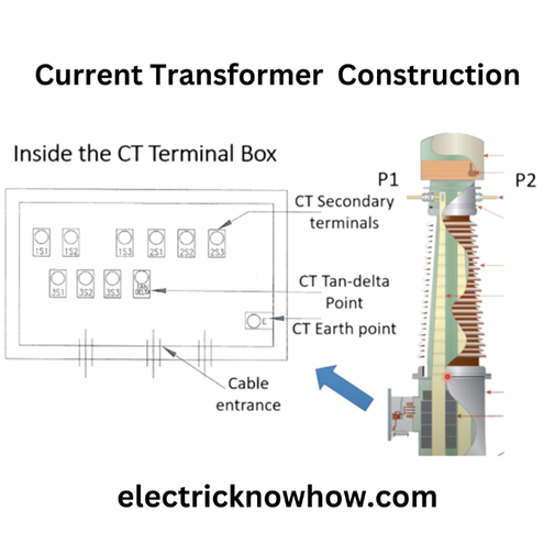
    Here P1 and P2 are primary terminals. In terminal boxes, we have 3 cores of CT from the secondary. We will test all that one by one in the next upcoming section.

    The basic requirement for this test is insulation resistance with connecting codes. In the construction of CT, we have primary and secondary sides. CT can operate on 66kV or 220kV or more value. This voltage on P1, and P2 is called the live point and CT is grounded. So there is a resistance value in between the live point and ground.

    Based on that value, we decide the working condition of CT in a power system. In the case of earth or low IR value by Megger Set, there will be more chances of flash in between the live and ground point.

    Performing IR Test:

    We need a Megger Set with connecting probes to measure the insulation resistance. It can measure insulation resistance on different voltage values. By pushing the test button on mete it can start working and providing values. 

    IR value test will be done by testing:

    • Primary to earth
    • Primary to Secondary
    • Secondary to earth
    • Core to Core (From Terminal Box) where the secondary terminal lies.

    We will connect the negative (black) probe with the earth which is the CT body at its bottom side. Next, we will connect a red (positive) probe on the primary terminal that is present on the upper side. Normally, we take the primary test at 5kV for one minute. You can note the values in the following table.

    Recording the Test Results:

    1. Place: Mention the Name of the Substation or Place
    2. Feeder/Transformer/spare: Write the Name of the Feeder or the Transformer
    3. Phase: R/Y/B
    4. CT Make, Serial Number & DOM: Say LAMCO/546544/01.05.2022
    5. Test Kit Make & Sr. No: Megger 12105
    6. Date of Calibration of the Test Kit:—/—/—–
    7. Atmospheric Condition: Sunny/rainy/ Cloudy    Ambient Temperature:
    8. Taken by: Name of the Engineer
    9. Test Voltage: 1KV/5KV
    10. Test Time: 30 sec
    Sr. No.ConnectionApplied VoltageResistance valueResult
    1Primary to Earth5kV—— MΩGood
    2Secondary to Earth Core-1500V—— MΩGood
    3Secondary to Earth Core-2500V—– MΩGood
    4Secondary to Earth Core-3500V—- MΩGood

    In the second case we will connect the red probe to the secondary in the CT terminal box and our negative probe will connect to earth as in the previous state. We will use 500V for the secondary site due to its less resistance as compared to the primary.  

    Normally we should get values higher than 100MΩ. A value below this indicates that our CT insulation is in bad condition and we should repair or replace that specific CT to prevent any further disturbance.   

    We have taken different values, but for practical measurement, you should note resistance between all connections to ensure the integrity of a current transformer. 

    Basic Precautions of Testing:

    Before testing the CT, you should verify the following conditions.

    • Breaker is in an off-state
    • Both isolators of CT are in open condition.
    • Secondary wires should be removed from the CT terminal box (from the ground).
    • Clean the surface of the insulating material to remove any dirt, moisture, or contaminants that could affect the accuracy of the test.

    Conclusion:

    We have studied the insulation resistance test in the case of the current transformer. These current transformers are important in getting the lower measured values of input current by dividing the incoming value depending on their CT different ratio. So its protection and safety are compulsory.

    current transformer
    Share. Facebook Twitter Pinterest LinkedIn Tumblr Email
    Previous ArticleWhat is an IR Value Test in a Circuit Breaker? An overview
    Next Article Ratio test of Current Transformer
    madhusmita
    • Website
    • Facebook
    • Instagram
    • LinkedIn

    Related Posts

    ⚡ Smart Grid in Distribution: Role, Challenges & Indian Scenario

    16 May 2025

    ⚡ Power Factor Correction in Distribution Systems

    16 May 2025

    ⚡ Voltage Drop in Distribution Lines: Causes, Calculation & Correction

    16 May 2025

    Comments are closed.

    Archives
    Categories
    • Distribution (15)
    • Generation (10)
    • Protection (24)
    • Q&A (7)
    • Switchgear (48)
      • Nameplate Details (2)
    • testing (11)
    • Transmission (20)
    Recent Posts
    • ⚡ Cable Types in Distribution: XLPE vs PILC vs Aerial Bundled Cables
    • ⚡ Smart Grid in Distribution: Role, Challenges & Indian Scenario
    • ⚡ Power Factor Correction in Distribution Systems
    • ⚡ Understanding Distribution Protection: Fuses, Relays & Reclosers
    • ⚡ Voltage Drop in Distribution Lines: Causes, Calculation & Correction
    Certification Course
    Electric Volt

    Quick Links

    • Home
    • About Us
    • Contact Us

    Post Categories

    • Generation
    • Transmission
    • Distribution
    • Protection
    • Switchgear
    • Q&A

    Vip Link

    • Privacy Policy
    • Disclaimer
    • Terms and Conditions

    Contact Us

    • [email protected]
    Linkedin