Close Menu
    Facebook X (Twitter) Instagram
    Trending
    • ⚡ Cable Types in Distribution: XLPE vs PILC vs Aerial Bundled Cables
    • ⚡ Smart Grid in Distribution: Role, Challenges & Indian Scenario
    • ⚡ Power Factor Correction in Distribution Systems
    • ⚡ Understanding Distribution Protection: Fuses, Relays & Reclosers
    • ⚡ Voltage Drop in Distribution Lines: Causes, Calculation & Correction
    • 🛠️ Distribution Transformer Maintenance: Checklist and Tips
    • INTRODUCTION TO SUBSTATION EARTHING
    • Maintenance of GIS (Gas-Insulated Switchgear)
    Electric Know How
    • Home
    • Generation
      • Hydropower Station
      • Thermal Power Station
      • DISTRIBUTED ENERGY SOURCES
      • Diesel Generator
      • Industrial Tools
      • DC System-Generating Stations
    • Transmission
      • High Voltage DC Transmission
      • High Voltage AC Transmission
        • Transmission line – An Overview
        • TRANSMISSION TOWER CONFIGURATION
        • Transmission Towers-Key Features
    • Distribution
      • ⚡ Understanding Electrical Distribution Systems: Basics to Architecture
      • ⚡ Top 5 Faults in Distribution Lines and How to Fix Them
      • 🛠️ Distribution Transformer Maintenance: Checklist and Tips
    • Protection
      • Power System Protection
        • Types of Fault in Power System
        • Relay Setting Calculation for Substation
        • Circuit Breaker
          • Nameplate details of SF6 Circuit Breaker
          • Major parameters of a circuit breaker
          • What is the use of an anti-pumping relay?
          • What is an IR Value Test in a Circuit Breaker? An overview
          • Testing of Circuit Breaker
        • Key Components of Control & Relay Panel
          • Relay Setting Calculation for Substation
          • Trip Circuit Supervision Relay
          • Three Phase Control Wiring
        • Switching Surges and Its Remedies
      • OVERVIEW OF TRANSFORMER PROTECTION
        • Differential Protection of Transformer
      • OVERVIEW OF GENERATOR PROTECTION
      • Distance Protection
      • Electrical Safety
    • Switchgear
      • Electrical Sub-Station
        • BATTERY SYSTEM IN GRID SUBSTATION
        • Operation of Float Cum Boost Charger
        • Protection Circuitry of Battery Charger
        • Power Transformer
          • INSULATION RESISTANCE OF TRANSFORMER
          • WTI AND OTI in Power Transformer
          • Transformer Oil Dielectric strength
          • On Load Tap Changing of Transformer
          • TRANSFORMER MAINTENANCE
        • Sub-Station Operation
        • Multiplying Factor for Energy Meter
      • Current Transformer
        • Nameplate Detail of Current Transformer – A Detail Guide
        • Current Transformer Knee Point Test – A Detailed Overview
        • What is a Current Transformer Polarity Test- Detailed Guide
        • Ratio test of Current Transformer
      • Potential Transformer
      • Isolator in Substation
        • Nameplate Detail of Isolators/Dis-connectors- A Detail Guide
      • Electrical Busbar
      • Insulators
      • Clamps and Connectors
      • Fire Fighting System
      • Lightening Arrester
        • LCM Test of a Lightning Arrestor – An Overview
      • Gas Insulated Substation
        • Local Control Cubicle
        • SF6 circuit breaker gas compartment
        • Maintenance of GIS (Gas-Insulated Switchgear)
    • Q&A
      • FAQS ON Current Transformer
      • POWER SYSTEM
      • FAQ ON BUSBAR
    Electric Know How
    Home»Generation»Thermal Power Station
    Generation

    Thermal Power Station

    madhusmitaBy madhusmita18 December 2022Updated:2 September 20231 Comment4 Mins Read
    Facebook Twitter Pinterest LinkedIn Tumblr Email
    Share
    Facebook Twitter LinkedIn Pinterest Email

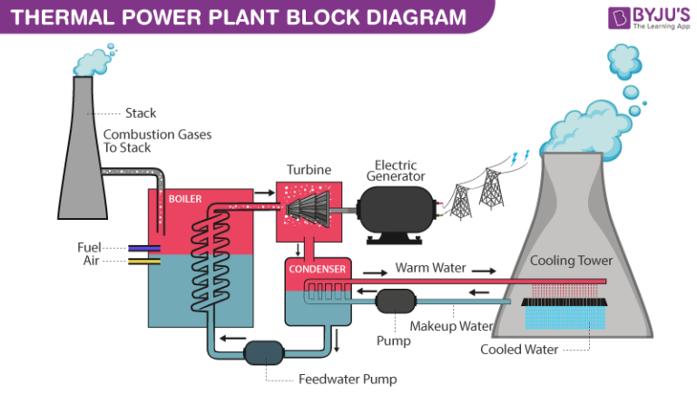
    A thermal power station, also known as a thermal power plant or simply a thermal plant, is a facility that generates electricity by burning fossil fuels or other heat sources to produce steam, which drives a turbine connected to an electrical generator. Thermal power stations are one of the most common types of power plants globally and have been a major source of electricity generation for many decades. Here is an overview of a typical thermal power station:.

    The coal, brought to the station by train or other means, travels from the coal handling plant by conveyor belt to the coal bunkers, from where it is fed to the pulverizing mills which grind it as fine as face powder. The finely powdered coal mixed with preheated air is then blown into the boiler by a fan called Primary Air Fan where it burns, more like a gas than as a solid in a convectional domestic or industrial grate, with an additional amount of air called secondary air supplied by Forced Draft Fan. As the coal has been grounded so finely the resultant ash is also a fine powder. Some of this ash binds together to form lumps which fall into the ash pits at the bottom of the furnace. The water-quenched ash from the bottom of the furnace is conveyed to pits for subsequent disposal or sale. Most of the ash, still in fine particle form is carried out of the boiler to the precipitators as dust, where it is trapped by electrodes charged with high-voltage electricity. The dust is then conveyed by water to disposal areas or to bunkers for sale while the cleaned flue gases pass on through ID Fan to be discharged up the chimney.

    Meanwhile, the heat released from the coal has been absorbed by the many kilometres of tubing which line the boiler walls. Inside the tubes is the boiler feed water which is transformed by the heat into steam at high pressure and temperature. The steam super-heated in further tubes (Super Heater) passes to the turbine where it is discharged through the nozzles on the turbine blades. Just the energy of the wind turns the sail of the windmill, so the energy of the steam, striking the blades, makes the turbine rotate.

     Coupled with the end of the turbine is the rotor of the generator – a large cylindrical magnet so that when the turbine rotates the rotor turns with it. The rotor is housed inside the stator having heavy coils of copper bars in which electricity is produced through the movement of the magnetic field created by the rotor. The electricity passes from the stator winding to the step-up transformer which increases its voltage so that it can be transmitted efficiently over the power lines of the grid.

      The steam which has given up its heat energy is changed back into the water in the condenser so that it is ready for re-use. The condenser contains many kilometres of tubing through which the colder is constantly pumped. The steam passing around the tubes loses the heat and is rapidly changed back to the water. But the two lots of water (i.e. boiler feed water & cooling water) must NOT MIX. The cooling water is drawn from the river, but the boiler feed water must be absolutely pure, far purer than the water we drink if it is not to damage the boiler tubes. Chemistry at the power station is largely the chemistry of water.

     To condense large quantities of steam, a huge and continuous volume of cooling water is essential. In most power stations, the same water is to be used over and over again. So the heat which the water extracts from the steam in the condenser is removed by pumping the water out to the cooling towers. The cooling towers are simply concrete shells acting as huge chimneys creating a draught (natural/mechanically assisted by fans) of air. The water is sprayed out at the top of towers and as it falls into the pond beneath it is cooled by the upward draught of air. The cold water in the pond is then circulated by pumps to the condensers. Inevitably, however, some of the water is drawn upwards as vapours by the draught and it is this which forms the familiar white clouds which emerge from the towers seen sometimes.

    Summary

    Thermal power stations have played a significant role in providing reliable electricity generation, but they also face challenges related to environmental impact, fuel availability, and the transition to cleaner energy sources. Many power utilities are investing in cleaner and more efficient technologies, such as advanced gas turbines and carbon capture and storage (CCS), to reduce their environmental footprint and adapt to changing energy trends.

    Share. Facebook Twitter Pinterest LinkedIn Tumblr Email
    Previous ArticleDISTRIBUTED ENERGY SOURCES
    Next Article Functions and Performance Requirements of Excitation Systems
    madhusmita
    • Website
    • Facebook
    • Instagram
    • LinkedIn

    Related Posts

    TYPES OF EXCITATION SYSTEM

    23 December 2022

    Functions and Performance Requirements of Excitation Systems

    23 December 2022

    DISTRIBUTED ENERGY SOURCES

    18 December 2022

    1 Comment

    1. Pingback: POWER SYSTEM - Learn With Electric Know How

    Archives
    Categories
    • Distribution (15)
    • Generation (10)
    • Protection (24)
    • Q&A (7)
    • Switchgear (48)
      • Nameplate Details (2)
    • testing (11)
    • Transmission (20)
    Recent Posts
    • ⚡ Cable Types in Distribution: XLPE vs PILC vs Aerial Bundled Cables
    • ⚡ Smart Grid in Distribution: Role, Challenges & Indian Scenario
    • ⚡ Power Factor Correction in Distribution Systems
    • ⚡ Understanding Distribution Protection: Fuses, Relays & Reclosers
    • ⚡ Voltage Drop in Distribution Lines: Causes, Calculation & Correction
    Certification Course
    Electric Volt

    Quick Links

    • Home
    • About Us
    • Contact Us

    Post Categories

    • Generation
    • Transmission
    • Distribution
    • Protection
    • Switchgear
    • Q&A

    Vip Link

    • Privacy Policy
    • Disclaimer
    • Terms and Conditions

    Contact Us

    • ele.mamohanty@optcl.co.in
    Linkedin