
Transmission towers are structures designed to support overhead power lines. Their configuration depends on voltage level, terrain, weather conditions, and the number of circuits they carry.
List of Content
¢PURPOSE OF TRANSMISSION TOWER
¢FACTORS GOVERNING TOWER CONFIGURATION
¢TOWER HEIGHT
¢ROLE OF WIND PRESSURE
¢SUMMARY
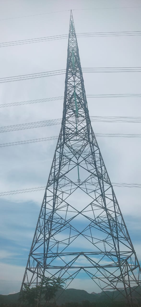
PURPOSE OF TRANSMISSION TOWER
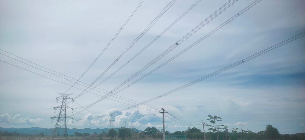
¢The electrical tower made up of steel and is used for supporting the conductor of transmission line
¢Air acts as insulating/dielectric medium in between.
Parts of The Transmission Tower
| Component | Function |
|---|---|
| Cross Arms | Hold the conductors |
| Insulators | Electrically isolate conductors from tower |
| Earth Wire (Ground Wire) | Protects from lightning |
| Tower Body | Main structure |
| Legs | Support the body and foundation |
| Foundation | Transfers load to the ground |
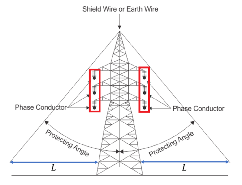
Shield angle
Configuration of a Transmission line tower
Depends on:
(a) The length of the insulator assembly.
(b) The minimum clearances to be maintained between conductors and between conductor and tower.
(c) The location of ground wire or wires with respect to the outermost conductor.
(d) The mid span clearance required from considerations of the dynamic behavior of conductors and lightning protection of the line.
(e) The minimum clearance of the lower conductor above ground level.
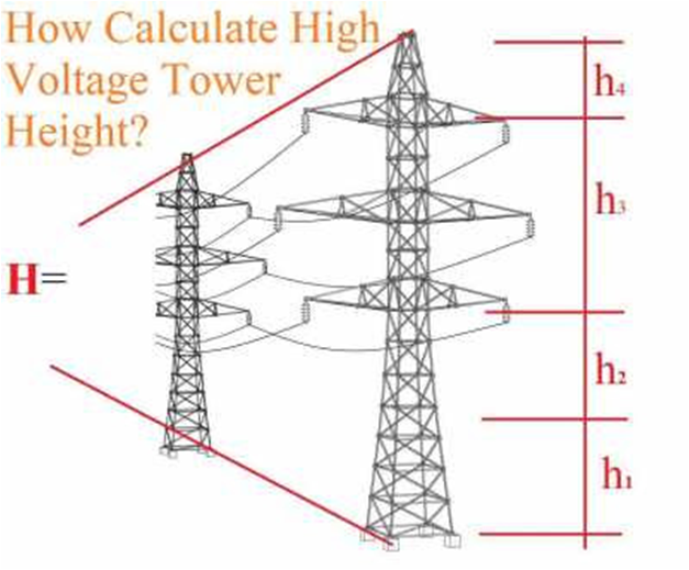
Factors governing the height of a tower
(a) Minimum permissible ground clearance (H1)
(b) Maximum sag (H2).
(c) Vertical spacing between conductors (H3).
(d) Vertical clearance between ground wire and top conductor (H4).
Thus the total height of the tower is given by
H = H1 + H2 + H3 + H4
Wind Zone
The country has been divided into six wind zones of different wind speeds.
| Wind Zone | Basic wind speed-m/s |
| 1 | 33 |
| 2 | 39 |
| 3 | 44 |
| 4 | 47 |
| 5 | 50 |
| 6 | 55 |
SUMMARY
¢The overall design of each tower is very closely connected with the user’s functional requirements. The requirements must be studied carefully before erection and commissioning.
