Close Menu
    Facebook X (Twitter) Instagram
    Trending
    • ⚡ Cable Types in Distribution: XLPE vs PILC vs Aerial Bundled Cables
    • ⚡ Smart Grid in Distribution: Role, Challenges & Indian Scenario
    • ⚡ Power Factor Correction in Distribution Systems
    • ⚡ Understanding Distribution Protection: Fuses, Relays & Reclosers
    • ⚡ Voltage Drop in Distribution Lines: Causes, Calculation & Correction
    • 🛠️ Distribution Transformer Maintenance: Checklist and Tips
    • INTRODUCTION TO SUBSTATION EARTHING
    • Maintenance of GIS (Gas-Insulated Switchgear)
    Electric Know How
    • Home
    • Generation
      • Hydropower Station
      • Thermal Power Station
      • DISTRIBUTED ENERGY SOURCES
      • Diesel Generator
      • Industrial Tools
      • DC System-Generating Stations
    • Transmission
      • High Voltage DC Transmission
      • High Voltage AC Transmission
        • Transmission line – An Overview
        • TRANSMISSION TOWER CONFIGURATION
        • Transmission Towers-Key Features
    • Distribution
      • ⚡ Understanding Electrical Distribution Systems: Basics to Architecture
      • ⚡ Top 5 Faults in Distribution Lines and How to Fix Them
      • 🛠️ Distribution Transformer Maintenance: Checklist and Tips
    • Protection
      • Power System Protection
        • Types of Fault in Power System
        • Relay Setting Calculation for Substation
        • Circuit Breaker
          • Nameplate details of SF6 Circuit Breaker
          • Major parameters of a circuit breaker
          • What is the use of an anti-pumping relay?
          • What is an IR Value Test in a Circuit Breaker? An overview
          • Testing of Circuit Breaker
        • Key Components of Control & Relay Panel
          • Relay Setting Calculation for Substation
          • Trip Circuit Supervision Relay
          • Three Phase Control Wiring
        • Switching Surges and Its Remedies
      • OVERVIEW OF TRANSFORMER PROTECTION
        • Differential Protection of Transformer
      • OVERVIEW OF GENERATOR PROTECTION
      • Distance Protection
      • Electrical Safety
    • Switchgear
      • Electrical Sub-Station
        • BATTERY SYSTEM IN GRID SUBSTATION
        • Operation of Float Cum Boost Charger
        • Protection Circuitry of Battery Charger
        • Power Transformer
          • INSULATION RESISTANCE OF TRANSFORMER
          • WTI AND OTI in Power Transformer
          • Transformer Oil Dielectric strength
          • On Load Tap Changing of Transformer
          • TRANSFORMER MAINTENANCE
        • Sub-Station Operation
        • Multiplying Factor for Energy Meter
      • Current Transformer
        • Nameplate Detail of Current Transformer – A Detail Guide
        • Current Transformer Knee Point Test – A Detailed Overview
        • What is a Current Transformer Polarity Test- Detailed Guide
        • Ratio test of Current Transformer
      • Potential Transformer
      • Isolator in Substation
        • Nameplate Detail of Isolators/Dis-connectors- A Detail Guide
      • Electrical Busbar
      • Insulators
      • Clamps and Connectors
      • Fire Fighting System
      • Lightening Arrester
        • LCM Test of a Lightning Arrestor – An Overview
      • Gas Insulated Substation
        • Local Control Cubicle
        • SF6 circuit breaker gas compartment
        • Maintenance of GIS (Gas-Insulated Switchgear)
    • Q&A
      • FAQS ON Current Transformer
      • POWER SYSTEM
      • FAQ ON BUSBAR
    Electric Know How
    Home»Switchgear»Current Transformer Knee Point Test – A Detailed Overview
    Switchgear

    Current Transformer Knee Point Test – A Detailed Overview

    madhusmitaBy madhusmita16 January 2024Updated:22 May 2024No Comments5 Mins Read
    Facebook Twitter Pinterest LinkedIn Tumblr Email
    Share
    Facebook Twitter LinkedIn Pinterest Email

    Current transformers play an important role in measuring electric current in our electric substations. To ensure their proper functioning, we need to perform proper testing on them as a knee point test. In this article, we are going to discuss a knee point test value test of a current transformer and how to perform this test.  

    Table of Contents

    Toggle
    • Knee Point Test in a Current Transformer
    • Why do we need Knee Point in CT?
    • CT Specifications
    • How Knee Voltage Occurs?
    • Knee Point Procedure
    • Basic Precautions of Testing:
    • Conclusion:

    Knee Point Test in a Current Transformer

    We have studied the functioning of current transformers as they help us to measure electric current by dividing input value by a specific CT ratio. Knee point voltage is the voltage of secondary winding in a current transformer. At the knee point, our CT will be in a saturation state (no change in flux further) due to a higher primary current. We can say, that at this saturation point, there will be no change in secondary current due to the maximum flux in the secondary core.   

    We need the following key components before starting the test:  

    • 0 to 230V VARIAC called variable transformer (these transformers help us to change the voltage with the help of a knob by caging tapping in winding).
    • Voltage Transformer 230/2000V (Step-up transformer)
    • Extension wire.
    • Clip on meter.
    • Volt Meter/Multi Meter (to measure voltages)

    These are required elements that we need before starting testing.

    Why do we need Knee Point in CT?

    We used PS Core CT for special protection like differential relays, distance relays, HT motors, and generators. Now if the voltage in the secondary increases by knee point voltage then, secondary winding does not feed accurate current as starts misbehaving with its current value with protection devices to which CT is connected.

    We can understand this by the following graph:  

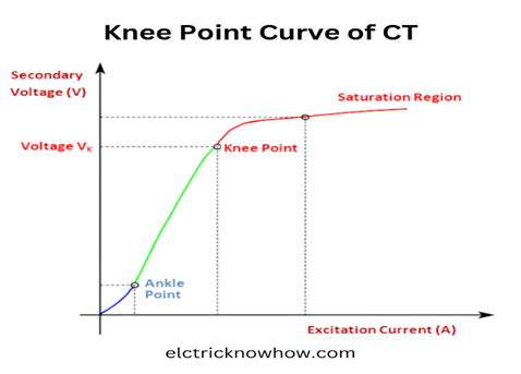
    You can see in this graph, we have excitation current on the horizontal axis and secondary voltages on the vertical axis. We apply voltage at the secondary and then there will be a point where the excitation current starts increasing beyond its limit. That point of maximum current gives us the knee point voltage.

    Ankle point at the start of the graph is used for the metering coil in CT.

    CT Specifications

    We need to study the nameplate of specific CT before starting the test. Here is an image representing the CT properties. Let’s read that first:

    Here are the following things:

    Vk = Knee Voltage Point = 950 volts

    Iex = Excitation Curret = 60mA at Vk/2

    These values are specific to this CT. It means that at the knee point voltage, the excitation current should not be more than 60mA.

    How Knee Voltage Occurs?

    As we know CT secondary is short, so how the secondary voltages are produced in the secondary of CT? The relay will be connected with the secondary and the relay will provide resistance with the leads/wires connected to the secondary. Core has also resistance when the current passes through the secondary (inducing in secondary with the help of primary current), a voltage will be produced. This voltage should not exceed tan knee point. In case of exceeding this voltage than knee point, the core will be saturated. After that, there will be mutual induction to transfer electric current from primary to secondary. You can see the CT diagram in the following image:

    Here are the primary (on the top side) and secondary side (in CT terminal box) with earth point.

    Knee Point Procedure

    Here is the procedure for the knee point voltage test:

    • First, we will make connections.
    • VARIAC output will go into the voltage transformer input.
    • The output of the voltage transformer will go in PS1 and PS3 in the terminal box of CT.
    • We will use a multimeter

    Basic Precautions of Testing:

    Before testing the CT, you should verify the following conditions.

    • Breaker is in an off-state
    • Both isolators of CT are in open condition.
    • Secondary wires should be removed from the CT terminal box (from the ground).
    • We will use a clip-on meter to measure the current in mA and a volt meter to measure the voltage.
    • After powering the supply to VARIAC, we will take values at different voltages by turning the knob.
    • We will measure current at specific VARIAC voltages.     
    • We have to take voltage to the knee point by turning the knee of VARIAC.

    Test results can be shown in the following table:

    Voltage Value (V)100200300400500600700800950110012001350
    Current Value (mA)2.54.55.77.28.710.312.314.5173155160

    Where knee point our specific CT is 950 V and saturation current is 60mA. We have checked values 10% more than our knee voltage value. You need to measure the voltage and current by your experiment and CT specifications.  You can make a graph using the above current and voltage to check the knee point as we have seen in the previous section of our article.

    Conclusion:

    We have studied the knee voltage test in the case of the current transformer. These current transformers are important in getting the lower measured values of input current by dividing the incoming value depending on their CT different ratio. So its protection and safety are compulsory. In this article, we have gone through the knee voltage value using VARIAC, voltmeter, and other key components.

    Share. Facebook Twitter Pinterest LinkedIn Tumblr Email
    Previous ArticleWhat is a Current Transformer Polarity Test- Detailed Guide
    Next Article LCM Test of a Lightning Arrestor – An Overview
    madhusmita
    • Website
    • Facebook
    • Instagram
    • LinkedIn

    Related Posts

    ⚡ Smart Grid in Distribution: Role, Challenges & Indian Scenario

    16 May 2025

    ⚡ Power Factor Correction in Distribution Systems

    16 May 2025

    ⚡ Voltage Drop in Distribution Lines: Causes, Calculation & Correction

    16 May 2025

    Comments are closed.

    Archives
    Categories
    • Distribution (15)
    • Generation (10)
    • Protection (24)
    • Q&A (7)
    • Switchgear (48)
      • Nameplate Details (2)
    • testing (11)
    • Transmission (20)
    Recent Posts
    • ⚡ Cable Types in Distribution: XLPE vs PILC vs Aerial Bundled Cables
    • ⚡ Smart Grid in Distribution: Role, Challenges & Indian Scenario
    • ⚡ Power Factor Correction in Distribution Systems
    • ⚡ Understanding Distribution Protection: Fuses, Relays & Reclosers
    • ⚡ Voltage Drop in Distribution Lines: Causes, Calculation & Correction
    Certification Course
    Electric Volt

    Quick Links

    • Home
    • About Us
    • Contact Us

    Post Categories

    • Generation
    • Transmission
    • Distribution
    • Protection
    • Switchgear
    • Q&A

    Vip Link

    • Privacy Policy
    • Disclaimer
    • Terms and Conditions

    Contact Us

    • ele.mamohanty@optcl.co.in
    Linkedin