

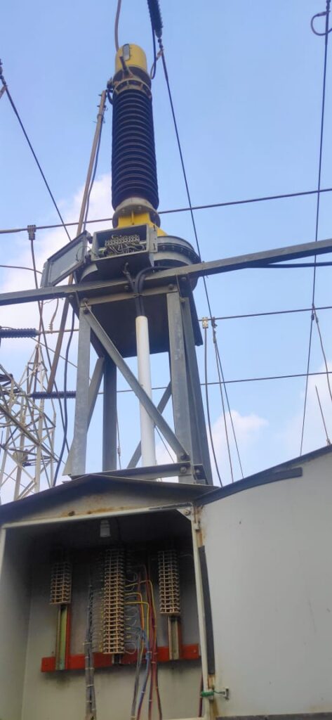
The ratio test of a current transformer (CT) is a crucial step in ensuring its accuracy and reliability in measuring current in a power system. Below is a general procedure for performing the ratio test on a current transformer located in Switchyard.
Safety Precautions:
Before starting the ratio test, it is essential to follow proper safety precautions. Ensure that the equipment is de-energized and properly isolated. Use appropriate personal protective equipment (PPE), and follow safety procedures to prevent accidents.
Equipment Required:
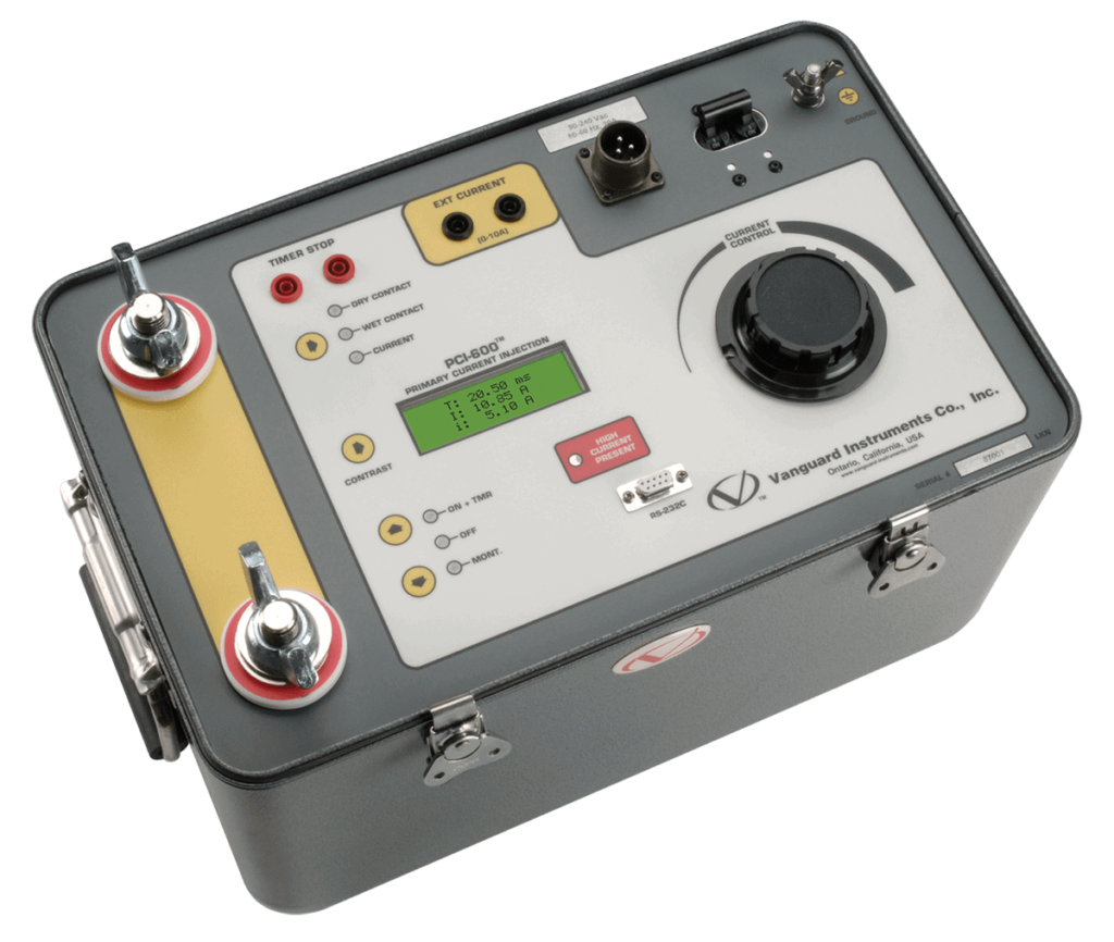
- CT Test Set
- Multi-ratio CT Test Switch Box
- CT Analyzer
- Secondary Injection Test Set
- Current and voltage sources
- Multimeter
- Wiring and connection accessories
Procedure:
Prepare the CT:
- Ensure that the CT is isolated from the power system.
- Verify that the CT is properly grounded.
- Inspect the CT for any visible damage or defects.
- Isolate CT:
- Physically isolate the CT from the power system to prevent any flow of current during the test.
- Check Connections:
- Verify that all connections are correct based on the CT’s primary and secondary ratings.
- Ensure proper polarization of the CT.
- Using the basic required components in the test, we will make the following connections and main procedure to conduct the ratio test:
- VARIAC output will go into the input of step up-current transformer.
- Then CT(another) output will go in the primary P1 of our main CT on which we are conducting the ratio test.
- The current that is coming out of P2 is injected in the CT (another) to make a current path.
- Current will enter from P1 and leave from P2.
- Now we will take output from the secondary terminal box.
- We can test on any of the 3 cores available in the secondary box. Then output will be from terminal 1 to terminal 2 or terminal 1 to terminal 3.
- For 1S1 and 1S2, we will short both of them, to get output from them.
- After shorting both terminals, we added a clip-on meter on primary and secondary take readings.
- By turning the knob of VARIAC, we can get the output current to inject in CT (another) input.
- VARIAC needs 220/240V of AC to start and to provide the output.
- We will set the primary to 30A b setting the value from VARIAC. Eventually the secondary will give us the 0.1A current. This is what we were looking for to test the terminal of 1S1 and 1S2. This ratio must be verified to check the beneficial results.
- Now if we check the ratio of 1S1 and 1S2, then by turning the knob of VARIAC. It will provide 30A in primary and 0.051A in secondary. As we know there is a 600 ratio, between the 1S1 and 1S2, so we achieve the 0.1A in secondary.
- Now if we check the ratio between the 1S1 and 1S3, we will get 0.1A in secondary by getting the 60A in primary from the clipboard.
- All output values will be shown on a clip-on meter and you should note those values.
| Sr. No. | P1 &P2 Current | Secondary Connections | Secondary Current | Output result |
| 1 | 30 | 1S1 TO 1S2 | 0.1 | Good |
| 2 | 60 | 1S1 TO 1S3 | 0.112 | Good |
| 3 | 30 | 2S1 TO 2S2 | 0.1 | Good |
| 4 | 60 | 2S1 TO 2S3 | 0.104 | Good |
| 5 | 30 | 3S1 TO 2S2 | 0.1 | Good |
| 6 | 60 | 3S1 TO 2S3 | 0.1 | Good |
Reconnect CT:
- After completing the test and ensuring that the CT is in good working condition, reconnect it to the power system.
Summary
We have studied the key components and procedures for conducting the ratio test using these elements. This test is conducted to ensure the reliability of the Current Transformer in our power system for its proper working.
Always follow the manufacturer’s instructions and industry standards when performing ratio tests on current transformers. It’s also recommended to consult with experienced personnel or hire professional testing services for critical equipment to ensure accuracy and safety.
