

INTRODUCTION
In the context of power generation and transmission, where circuit isolation during faults and minimizing disruptions is vital, primary safeguards for this transmission line and power transformer include differential protection and distance protection. Recognizing potential issues such as differential communication failures or trips, backup protection was programmed in the form of overcurrent and earth fault protection. These relay setting calculations have to be done carefully to ensure system reliability.
Fault Analysis:
Conduct a thorough fault analysis to identify potential fault scenarios within the primary substation. Consider various fault types, locations, and magnitudes.
Equipment Characteristics:
Understand the impedance and admittance characteristics of the substation equipment, such as transformers, transmission lines, circuit breakers, and busbars. Relay settings should account for the specific response requirements of each element.
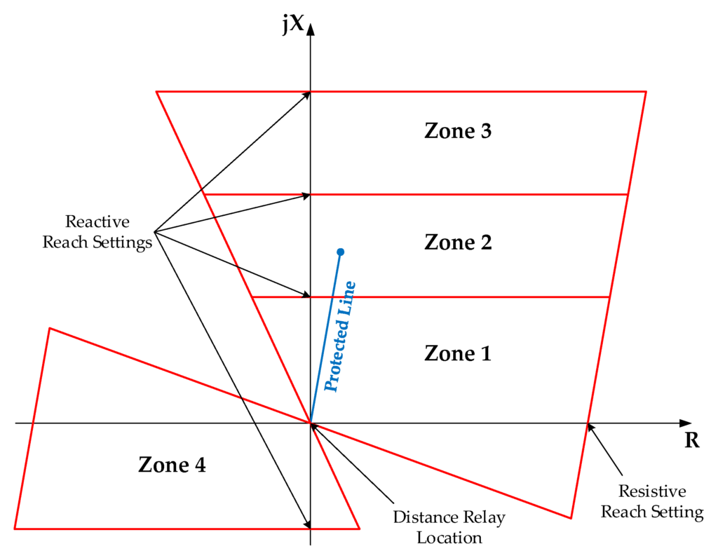
Impedance characteristic –
protected Line-
PTR 400KV/110V.
CTR -800 A/ 1A
Z1=0.03+0.31j per km
Z0=0.22+0.98j per km
Line length: 80km
Transformer capacity 160 MVA
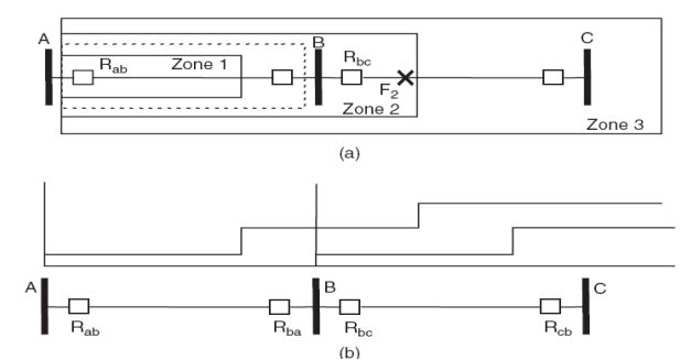
Coordination with Other Relays:
Coordinate the settings of relays within the substation to ensure proper discrimination and selectivity. This involves adjusting time-current characteristics to allow the closest relay to clear the fault without affecting downstream protection.
Shortest Adjacent line (SAL).
21 =0.03+ 0.31j/km
Z0= 0.22+0.98j/km
Line Length= 30km
Longest adjacent line (LAL)
line length = 125km.
Z1= 0.03+0.31j/km
Z0= 0.22+0.98j/km
Setting
Z1 =80% of Protected line
22 =100% Protected fine + 50% of SAL
Z3 =100% Protected line +100%of LAL
Z4= 25% PL
Time-Current Curves:
Develop time-current curves for the protective relays. These curves depict the relationship between fault current magnitude and the corresponding operating time of the relay.
Backup Protection:
Implement backup protection schemes, ensuring that secondary protection is in place if the primary protection fails. Backup relays should have settings that complement the primary protection.
•51 relay protection is time-delay overcurrent protection, designed to detect and interrupt overcurrent conditions that persist for a certain period, such as those caused by overloading or ground faults.
•50 protection operates quickly and is used as primary protection for power system elements like transformers, generators, and transmission lines.
Relay Setting Calculation for Remote End Grid Station:
Transmission Line Characteristics:
Consider the characteristics of the transmission lines connecting the remote end grid station. Fault currents, line lengths, and impedance values are critical parameters for relay setting calculations.
calculation
Zprotected line = 0.03 + J 0·31 / Km
Length=80km
= 24.88<84.47
Z SAL = 0.03+j0.31/Km
Length:20 km
= 6.22<84.47
Z LAL = 0.03+j0.31/km
length= 140 km
= 43.54<84.47
Transformer and Equipment Settings:
Similar to primary substations, understand the settings required for transformers, circuit breakers, and other equipment at the remote end grid station. Adjust relay settings accordingly.
Communication Delays:
Account for communication delays, especially in remote grid stations where communication links may introduce time lags. This is crucial for coordinated protection with adjacent substations.
Remote Control and Automation:
Incorporate settings related to remote control and automation features. This includes setting communication protocols, addressing remote tripping, and ensuring proper coordination with centralized control systems.
Integration with System Protection:
Ensure that relay settings align with broader system protection strategies. Collaborate with neighboring grid stations to establish coordinated protection schemes that cover a wider area.
Summary
Relay setting calculations for the incoming feeder or outgoing feeder of a grid substation are crucial for maintaining the reliability and stability of the electrical grid. A thorough understanding of fault scenarios, system configuration, and coordination requirements is essential in configuring effective relay settings.
