
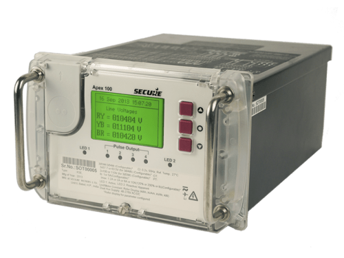
The Apex 100 Energy meter is a type of electronic energy meter used for measuring the amount of electrical energy consumed for a particular feeder in Grid Sub-Stations.
Here is a general working principle of the Apex 100 Energy meter:
The meter is connected to the electrical panel of a specific feeder through cables that are connected to CT and PT.
It measures the electrical energy consumed by reading the voltage and current flowing through the circuit.
The data is processed by an embedded microcontroller and stored in its memory.
The meter may also have communication capabilities for remote reading and monitoring.
The accuracy of the meter is maintained by regular calibration and testing.
Overall, the Apex 100 Energy meter works by continuously monitoring the electrical parameters and recording the energy consumption over a given time period. This information can help individuals and organizations make informed decisions regarding energy conservation and cost management.
Wiring of Energy Meter
The wiring of the Apex 100 Energy meter may vary depending on the specific installation and electrical system. However, here are some general guidelines:
Make sure the electrical power is turned off before beginning any wiring work.
The meter typically has three input terminals, labeled L1, L2, and L3, for the three-phase power supply.
The meter may also have two output terminals for the measurement of current, labeled CT1 and CT2.
The CTs (current transformers) should be connected to the load lines, and their polarity should be observed.
The voltage connections should be made to the L1, L2, and L3 terminals.
It is important to note that incorrect wiring can result in damage to the meter or inaccurate readings.
It is important to note that wiring should only be done by a qualified electrician to ensure proper installation and to prevent any damage or harm from occurring.
Calibration of Energy Meter
Calibrating an energy meter typically involves comparing its readings with a known reference to ensure accuracy. Here’s a general overview of the calibration process for an energy meter:
- Obtain a Reference Meter: You will need a calibrated reference meter that is traceable to a recognized standard. This reference meter should have higher accuracy and be calibrated by an accredited calibration laboratory.
- Prepare Test Setup: Set up a test bench or test environment with appropriate electrical connections, including the necessary power supply, current shunts, voltage dividers, and any other equipment needed for the specific type of energy meter being calibrated.
- Verify Test Bench Accuracy: Before proceeding with the calibration, verify the accuracy of the test bench or test environment by calibrating the reference meter against a known standard to ensure that it is providing accurate and reliable measurements.
- Connect the Energy Meter: Connect the energy meter to be calibrated to the test bench or test environment, following the manufacturer’s instructions and industry standards for electrical connections.
- Perform Calibration: Energize the test bench or test environment with the appropriate voltage and current levels, and record the readings from both the energy meter being calibrated and the reference meter simultaneously. Repeat the measurements for different test points or load conditions as required.
- Calculate Calibration Factors: Analyze the measurement data and calculate calibration factors or correction coefficients to adjust the readings of the energy meter being calibrated. This may involve using statistical methods or mathematical formulas to determine the calibration factors based on the measured values.
- Apply Calibration Factors: Apply the calculated calibration factors to the energy meter being calibrated, either by adjusting its settings or by applying correction factors during data analysis, depending on the type of energy meter and its calibration method.
- Verify Calibration: Verify the accuracy of the calibrated energy meter by comparing its readings with the reference meter at different test points or load conditions. If the readings are within the acceptable tolerance limits, the calibration is considered successful.
- Document Calibration Results: Record and document all calibration results, including the measurement data, calibration factors, and any adjustments made to the energy meter being calibrated. This documentation is important for traceability and quality assurance purposes.
It’s important to note that energy meter calibration may require specialized knowledge, equipment, and expertise and should be performed by qualified personnel or accredited calibration laboratories to ensure accuracy and reliability. Always refer to the manufacturer’s instructions and industry standards for proper calibration procedures for your specific type of energy meter.
